
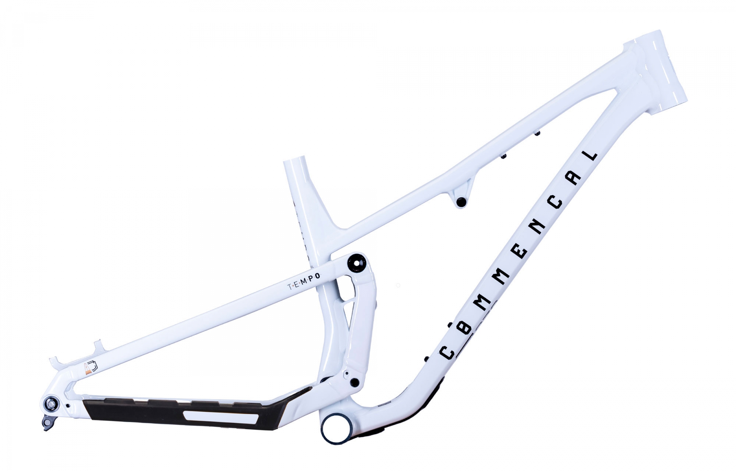
Congratulations on the purchase of your COMMENCAL T.E.M.P.O. frame!
The first step of the build is the internal cable routing and headset installation.
Here are some instructions to help you.
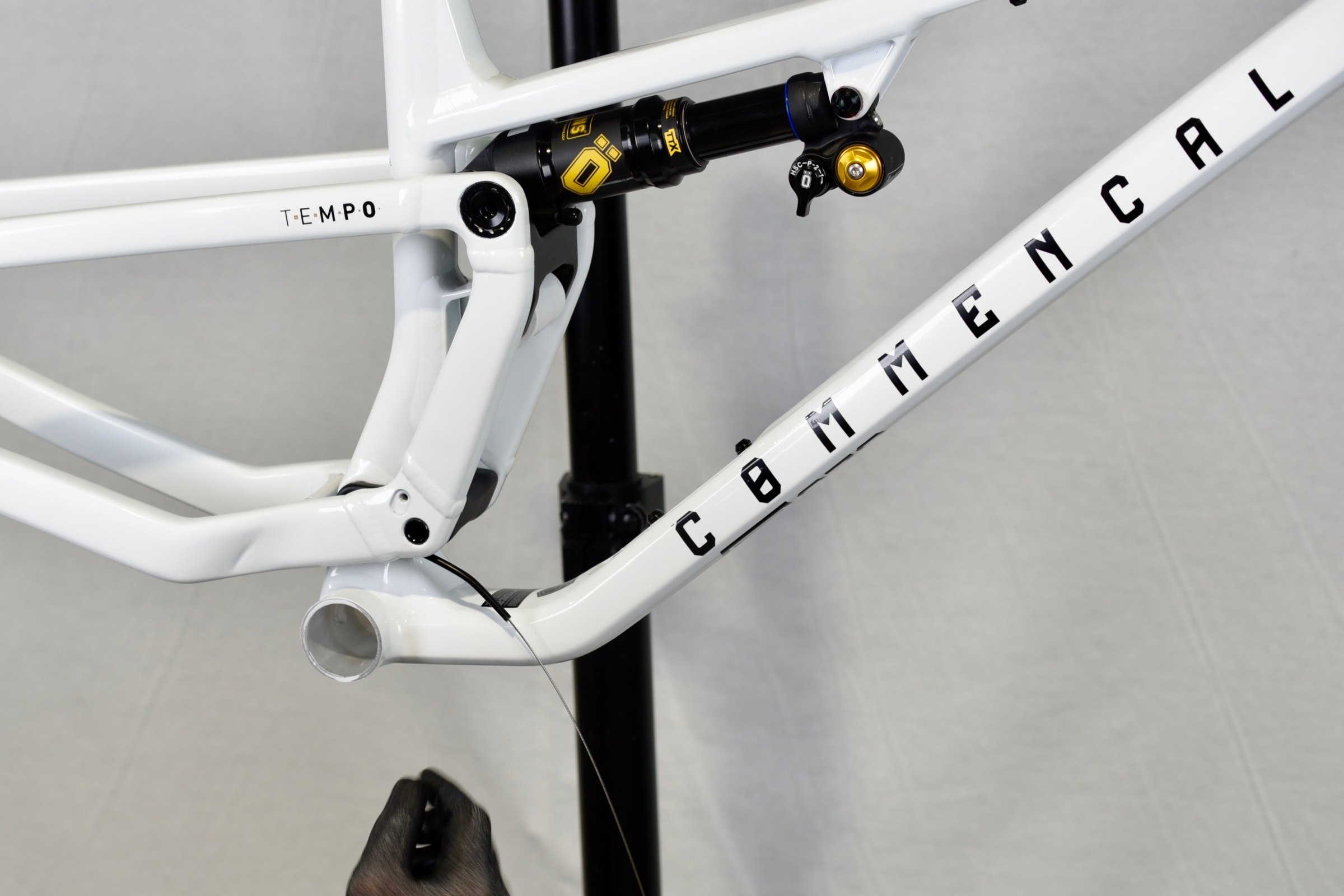
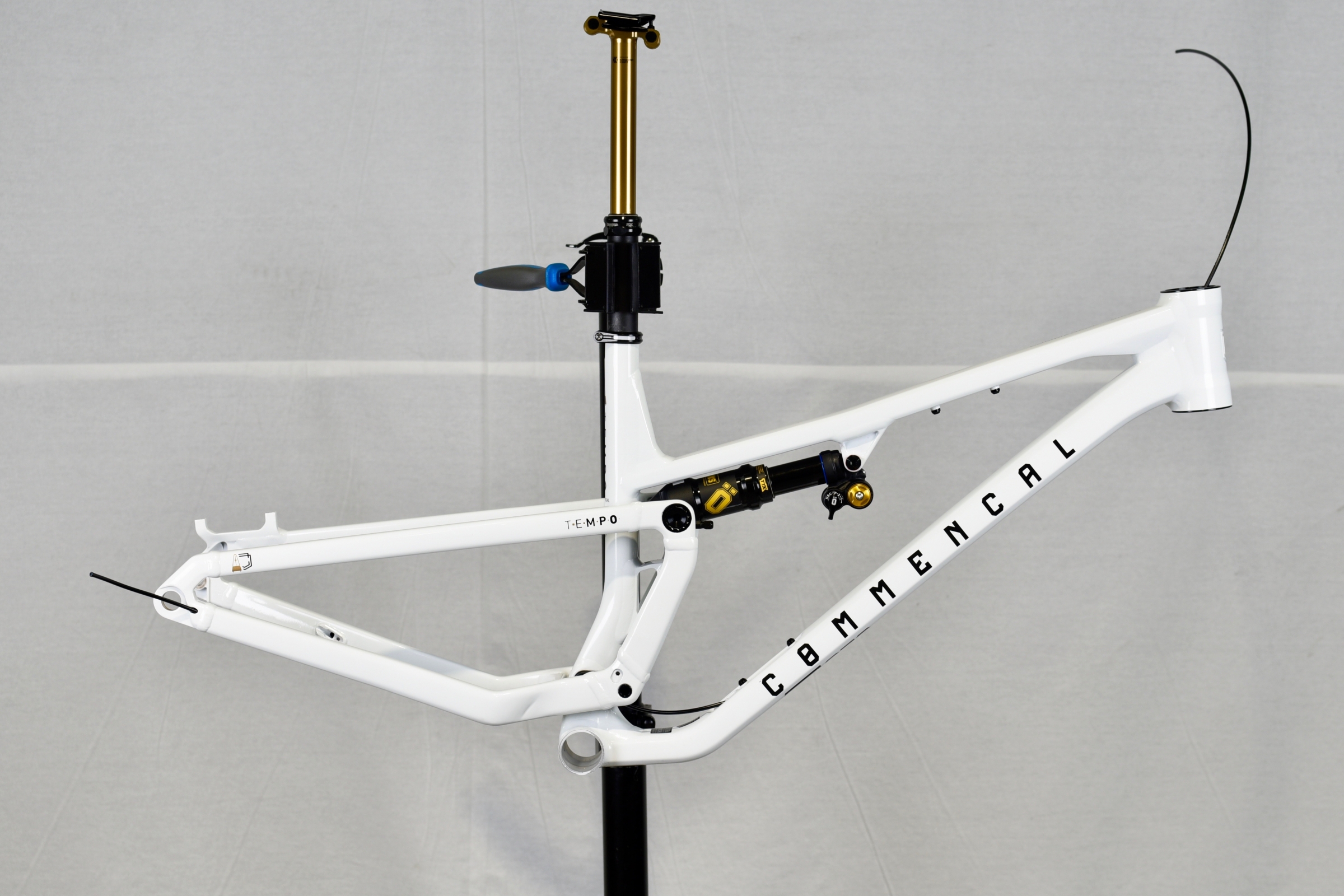
Fix your T.E.M.P.O. frame onto a bike stand with the seat clamp and dropper post already assembled.
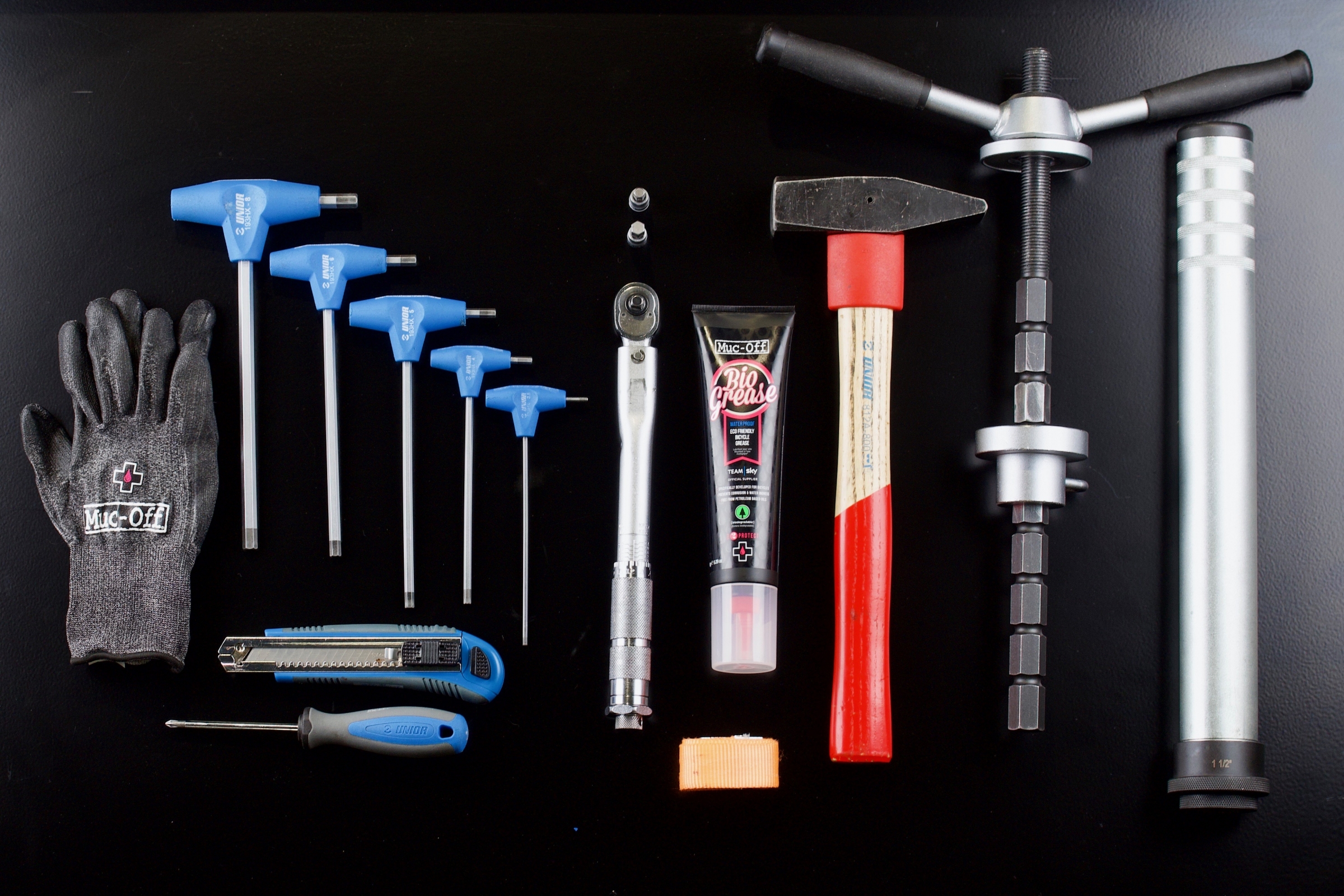
Prepare the necessary tools before you start:
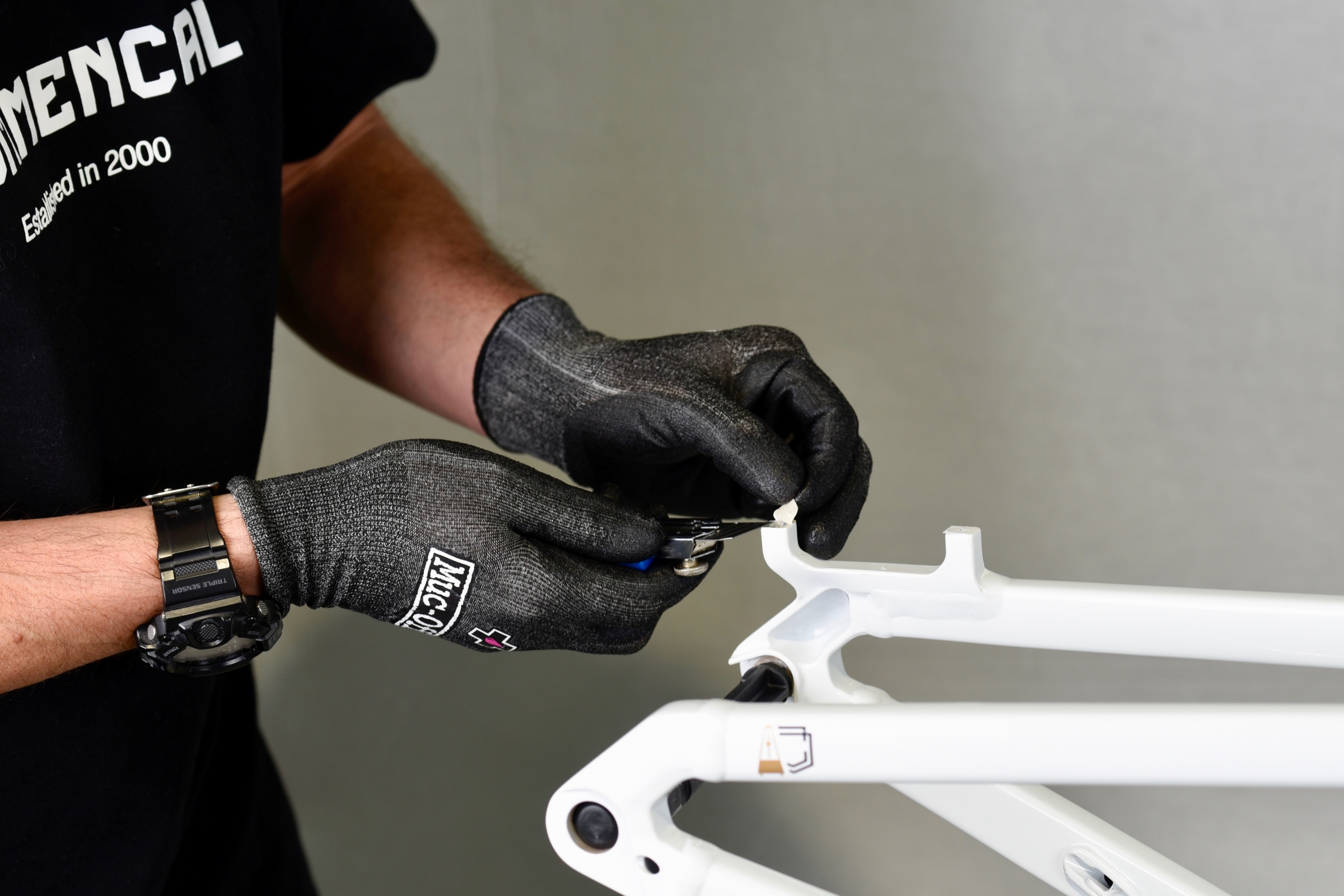
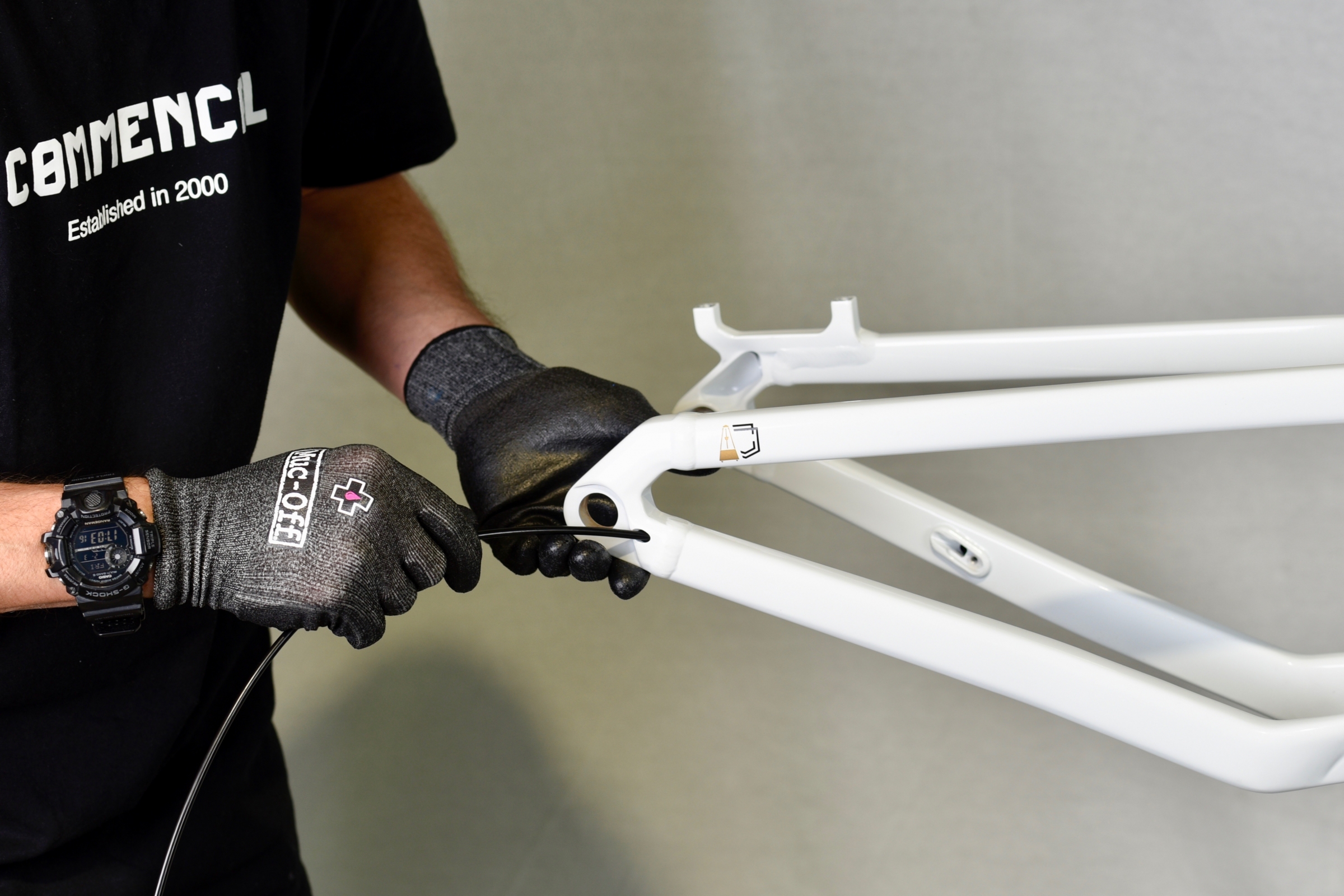
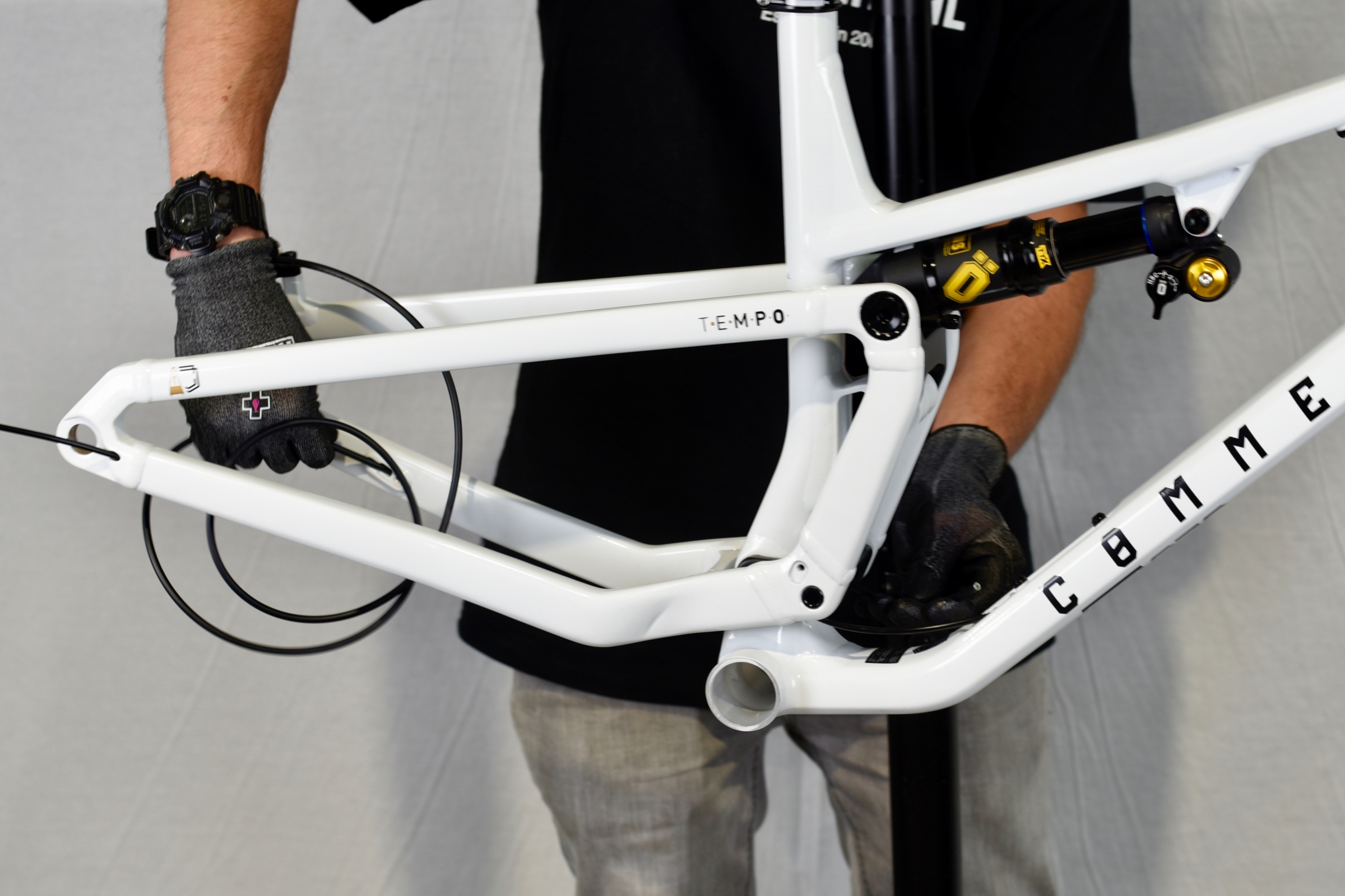
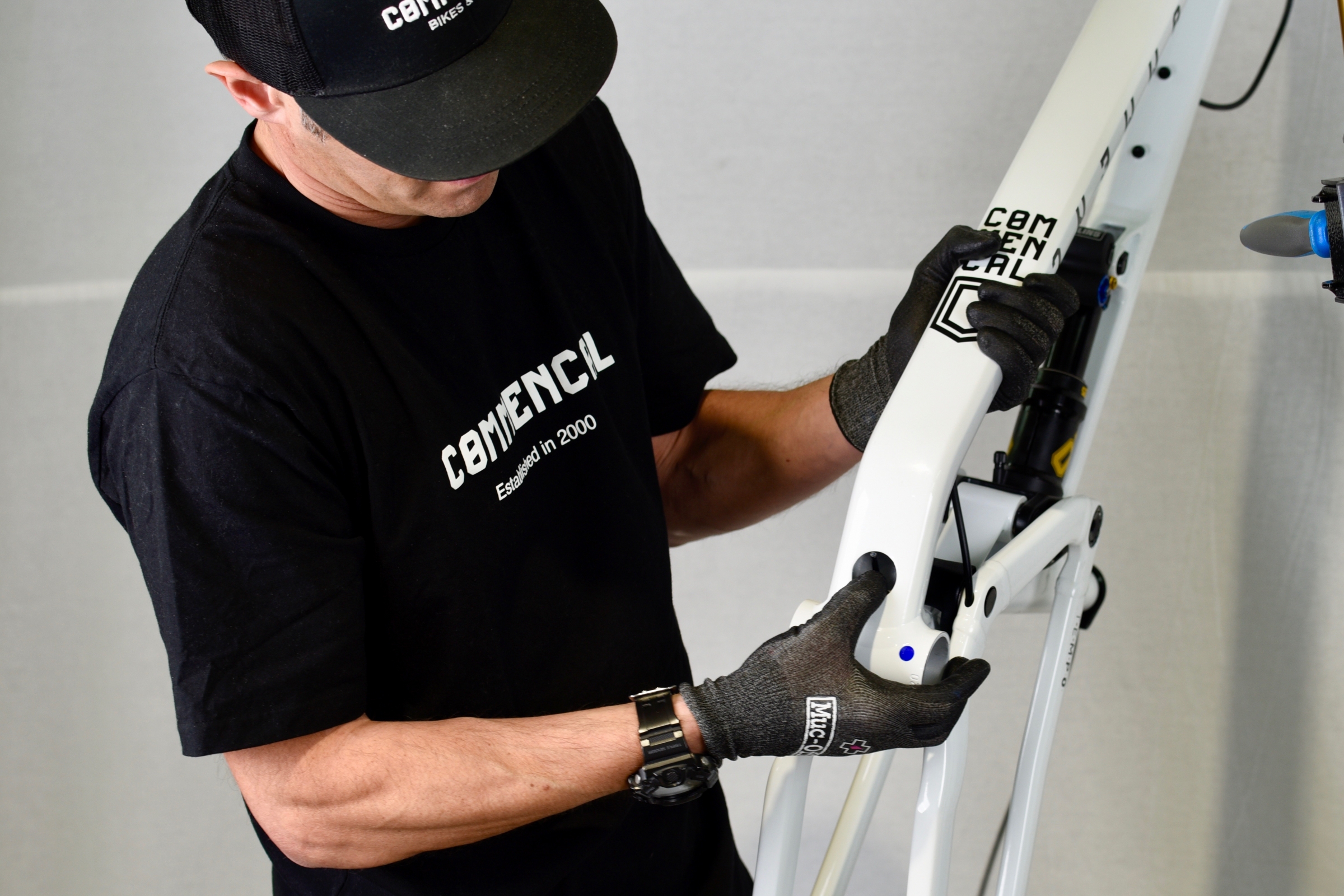
With the cutters, remove the paint masks from the brake mounts.
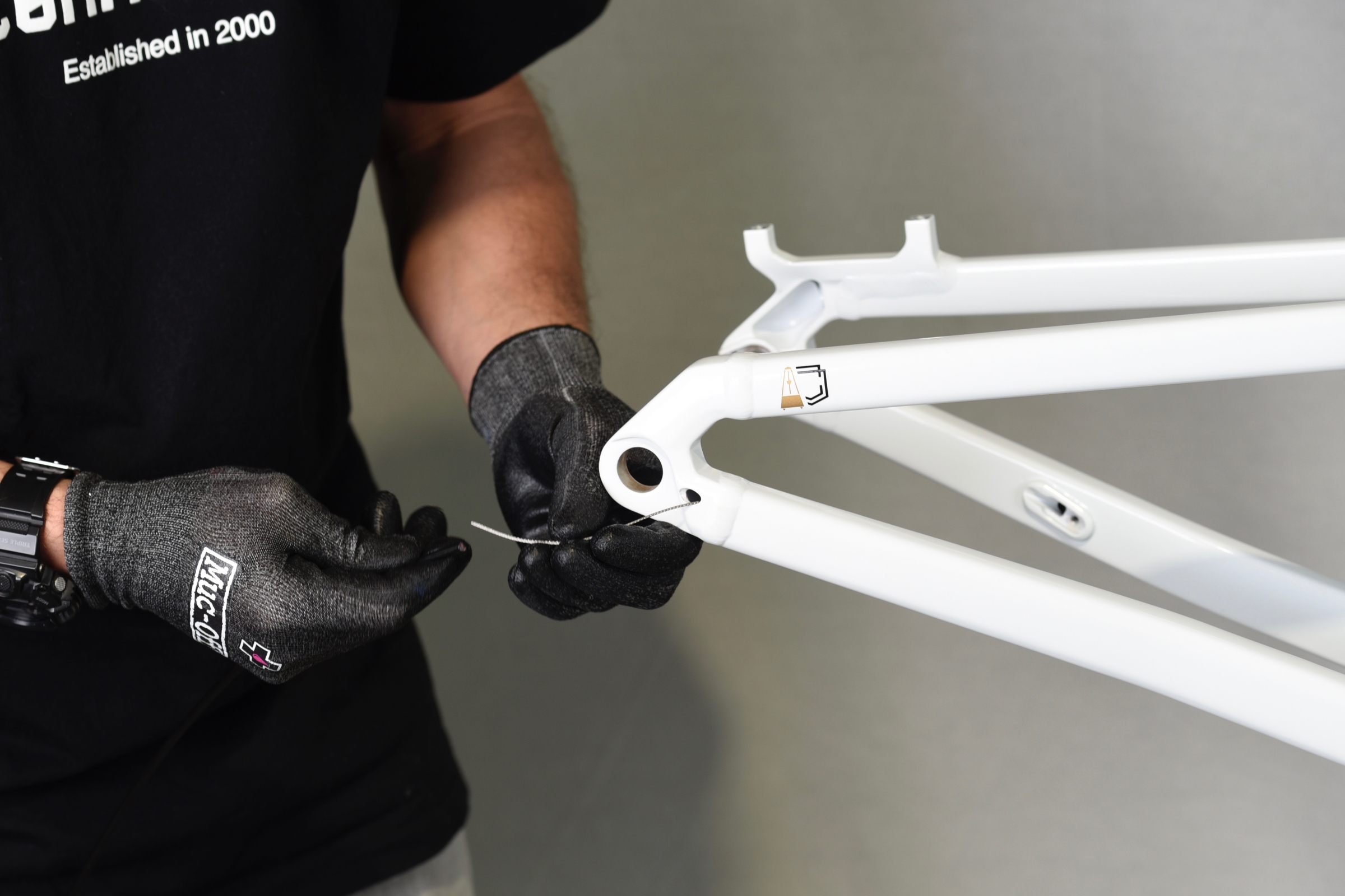
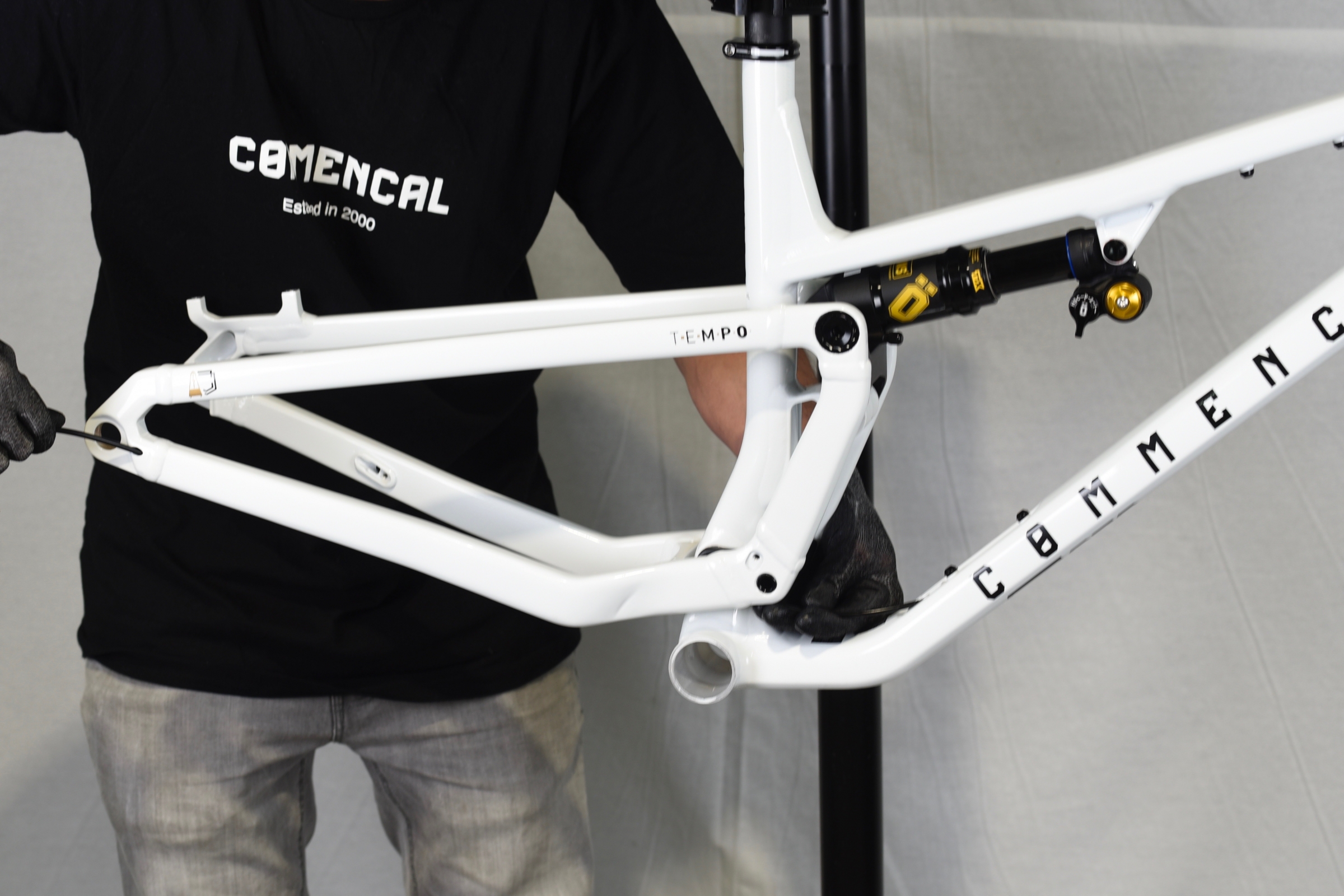
With the cutters, remove the paint masks from the chain stay cable routing hole.
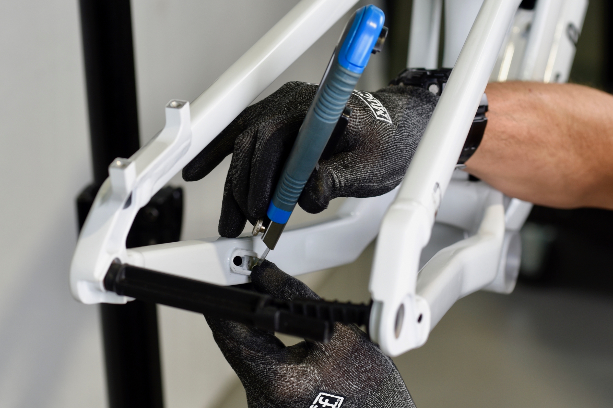
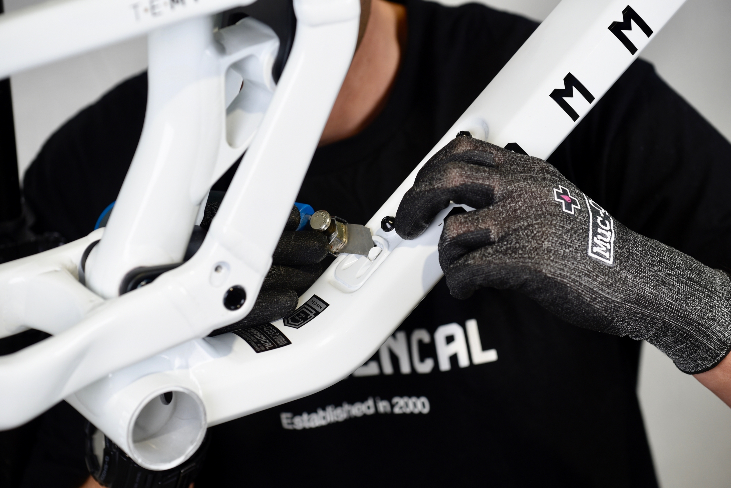
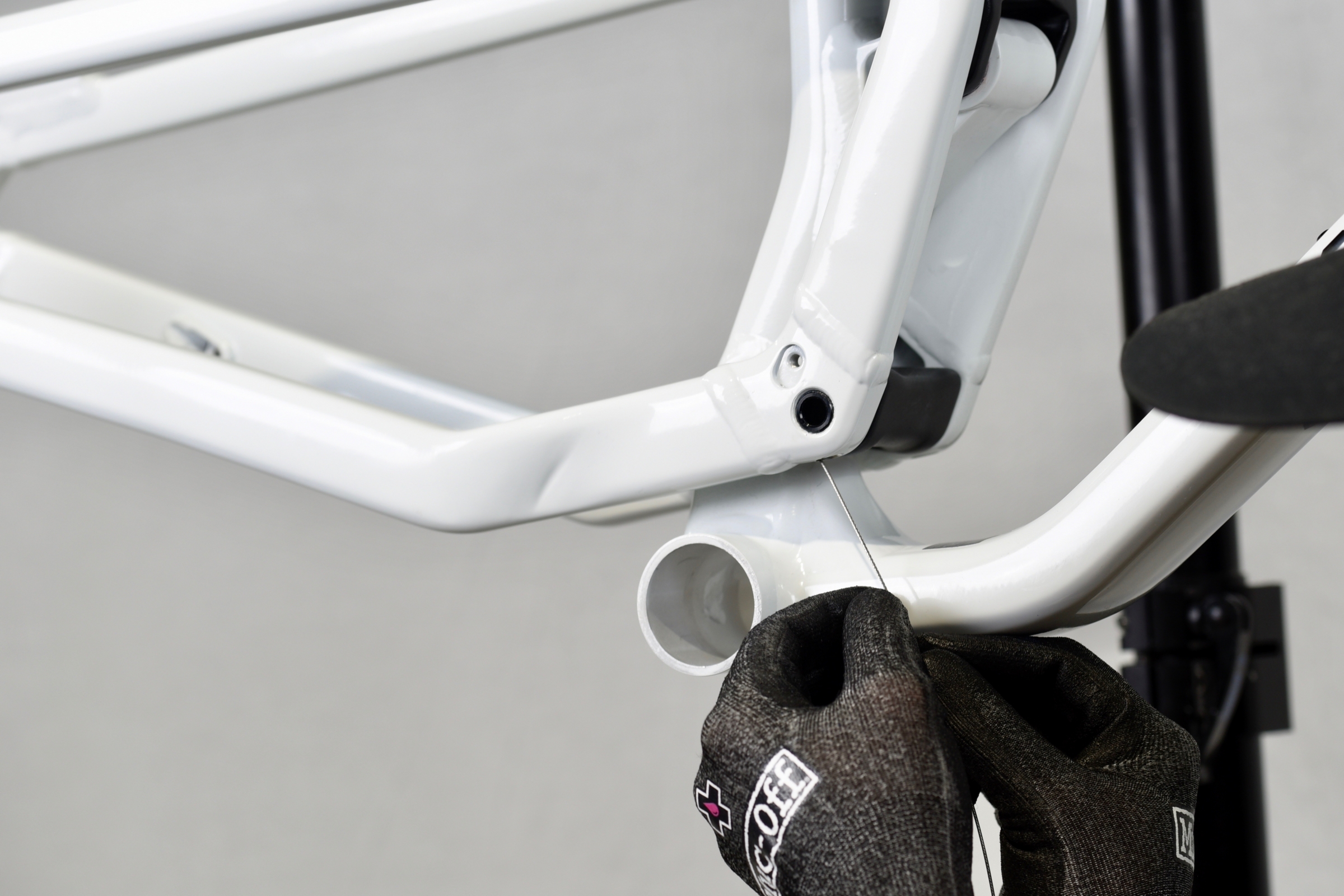
With the cutters, remove the paint masks from the down tube routing hole.
To install your shock, you will need to rotate the upper link forward.
With an 8mm Allen key, remove the rear triangle/upper link axles.
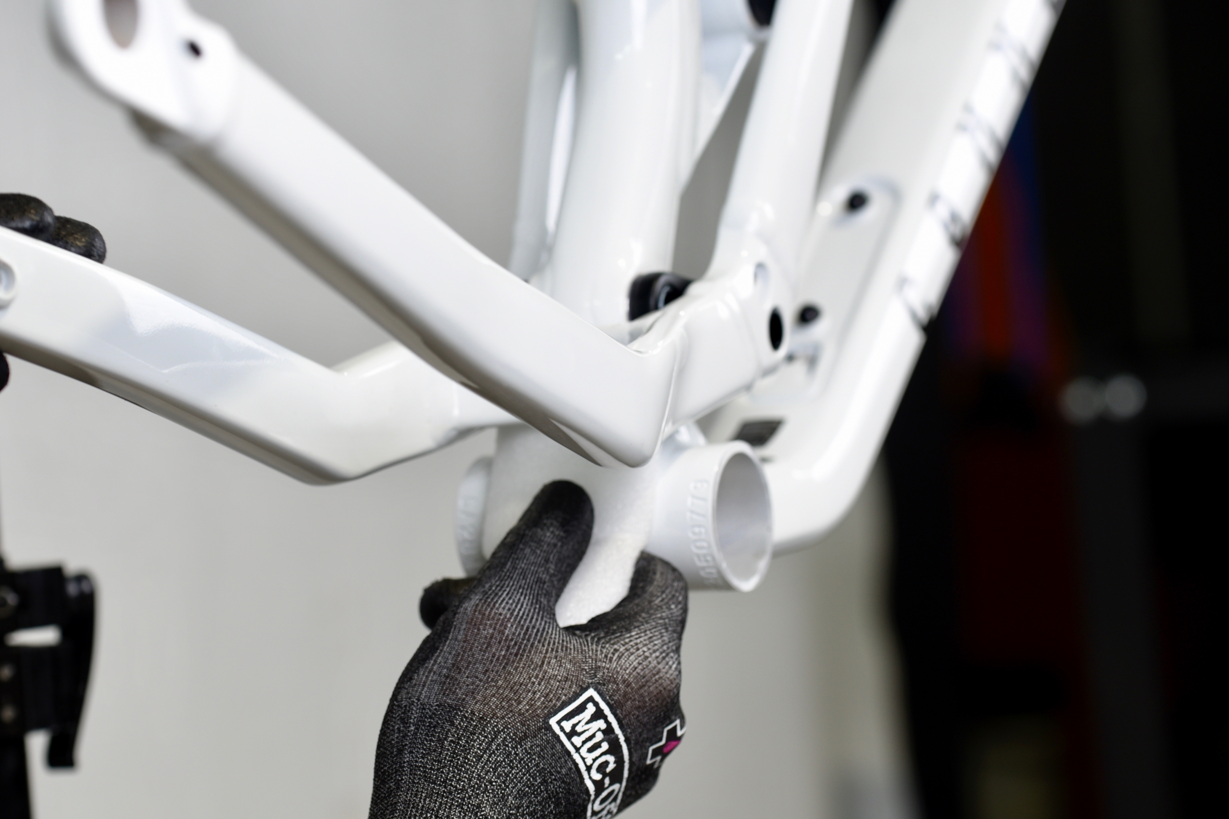
To avoid rear triangle/front triangle contact, and to protect the paint, place a piece of foam behind the rear triangle bridge.
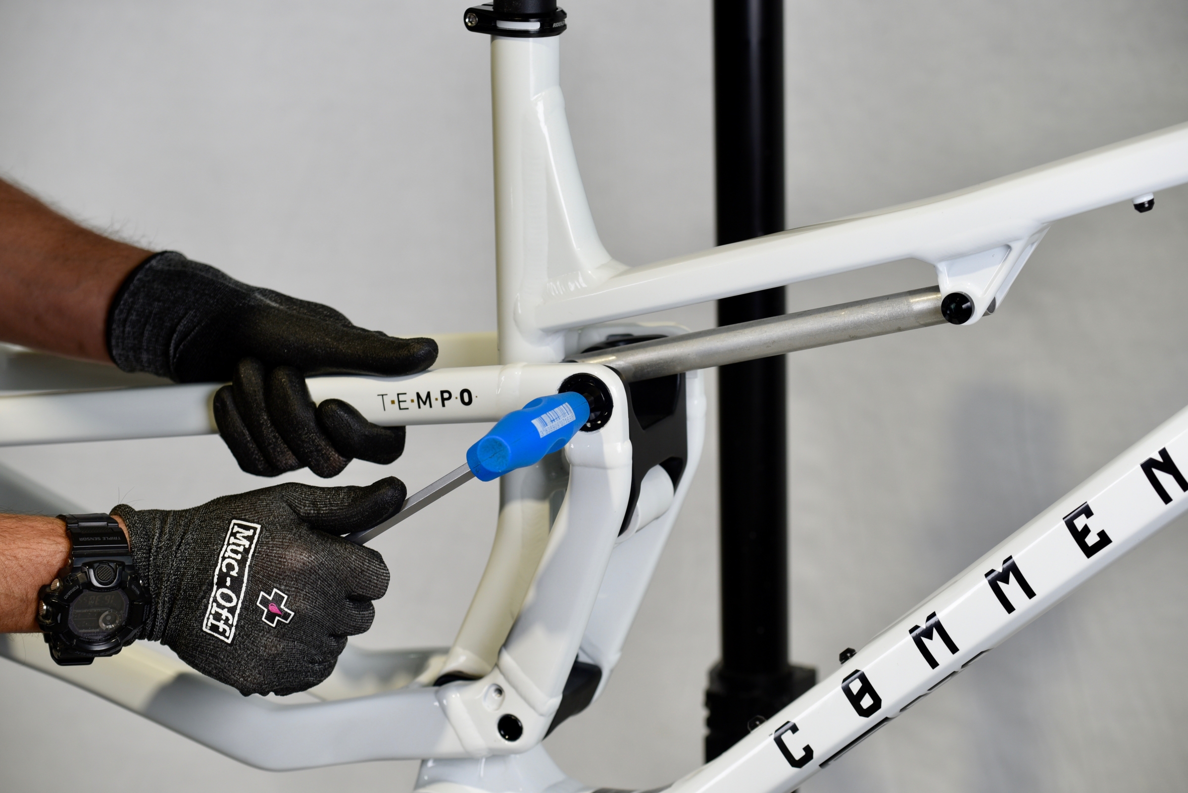
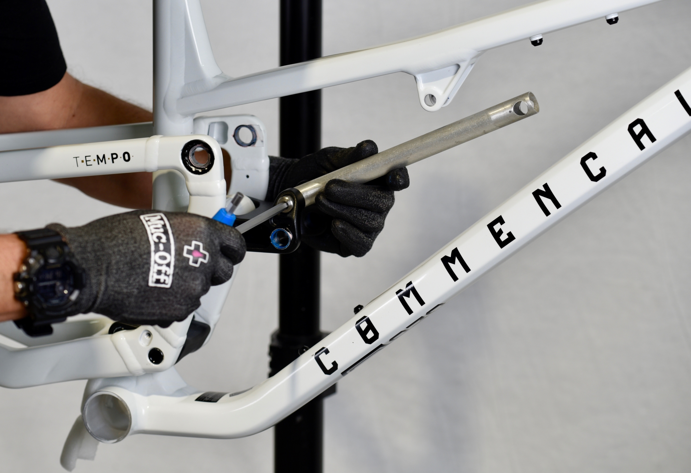
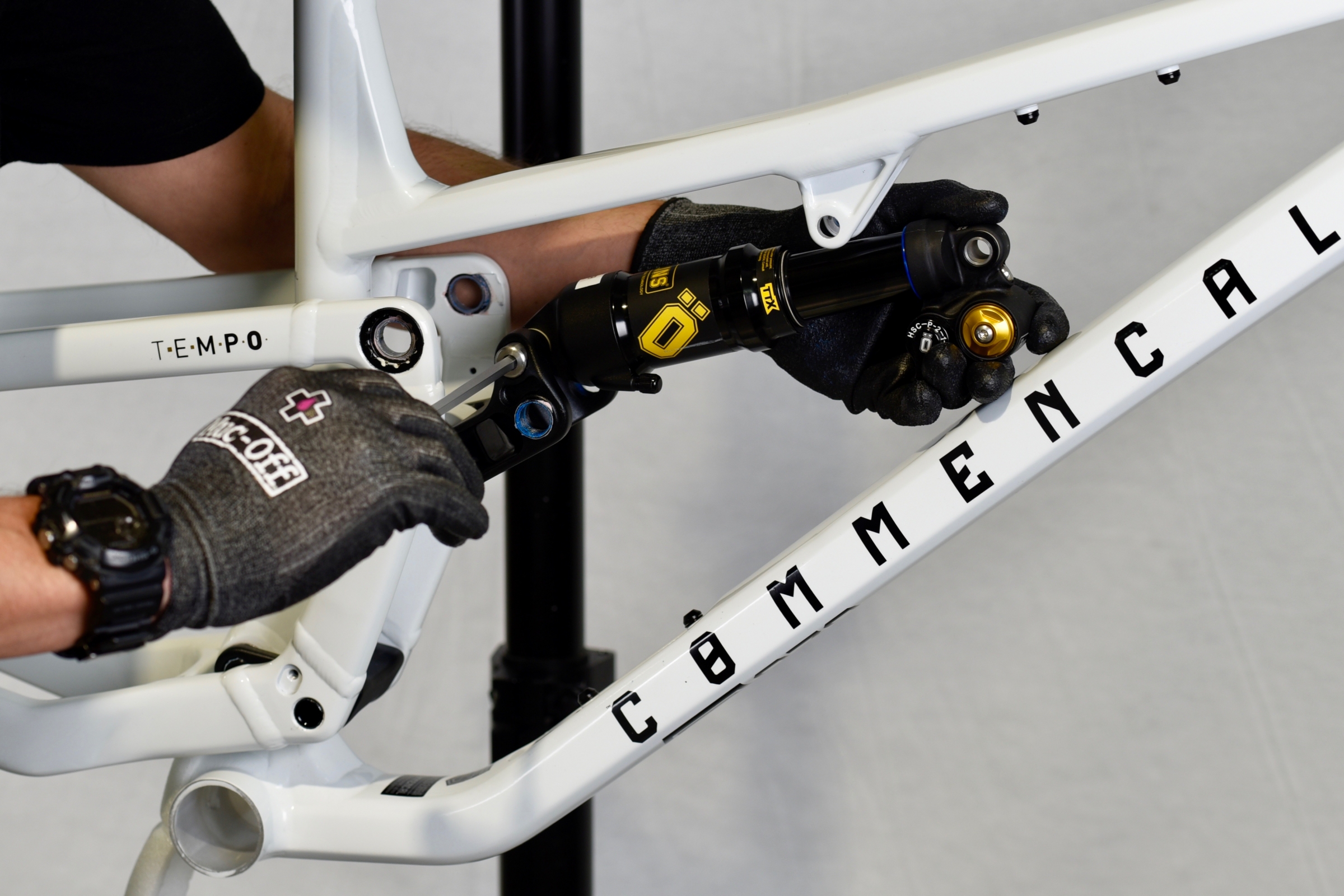
With a 6mm Allen key remove front triangle/shock axle.
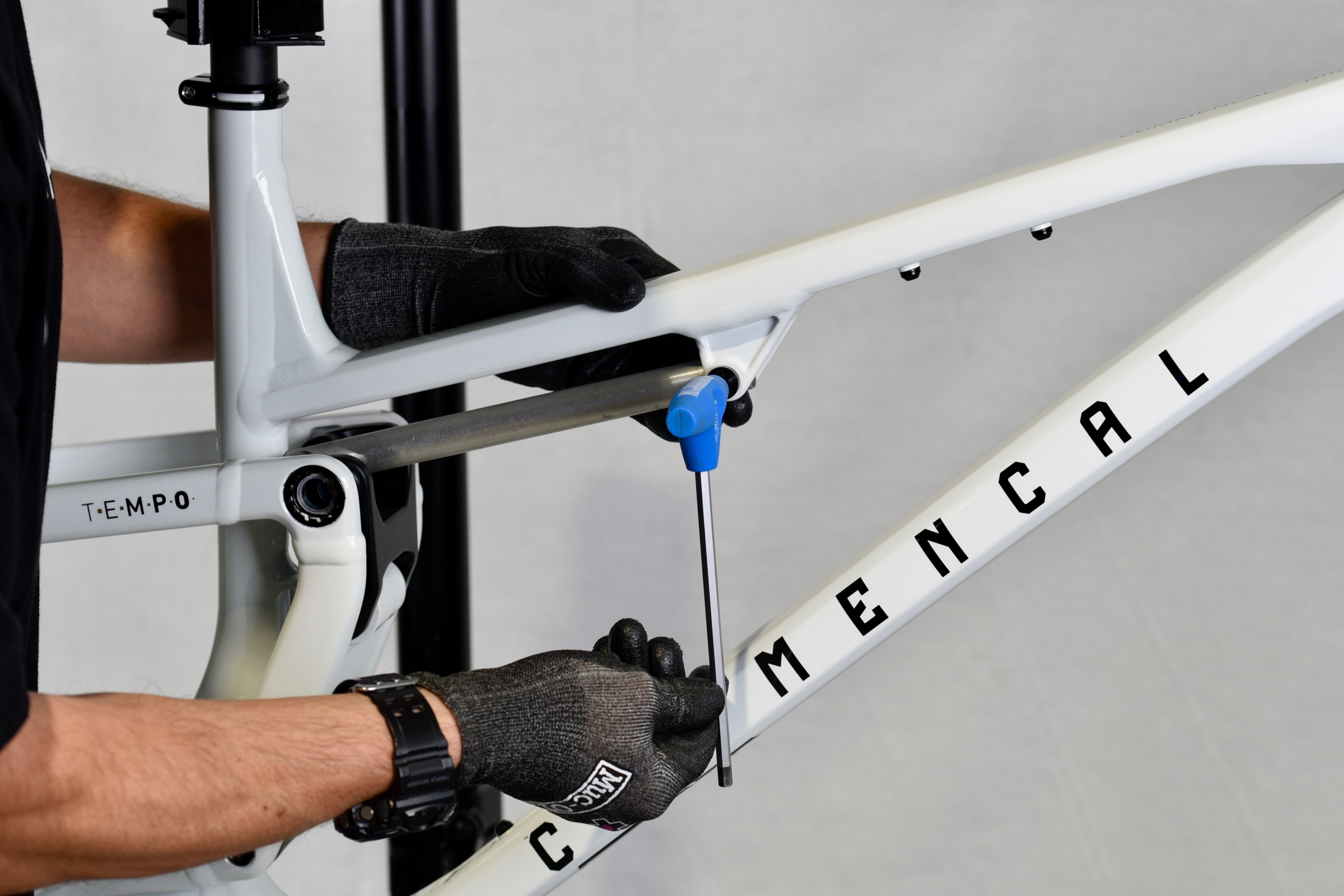
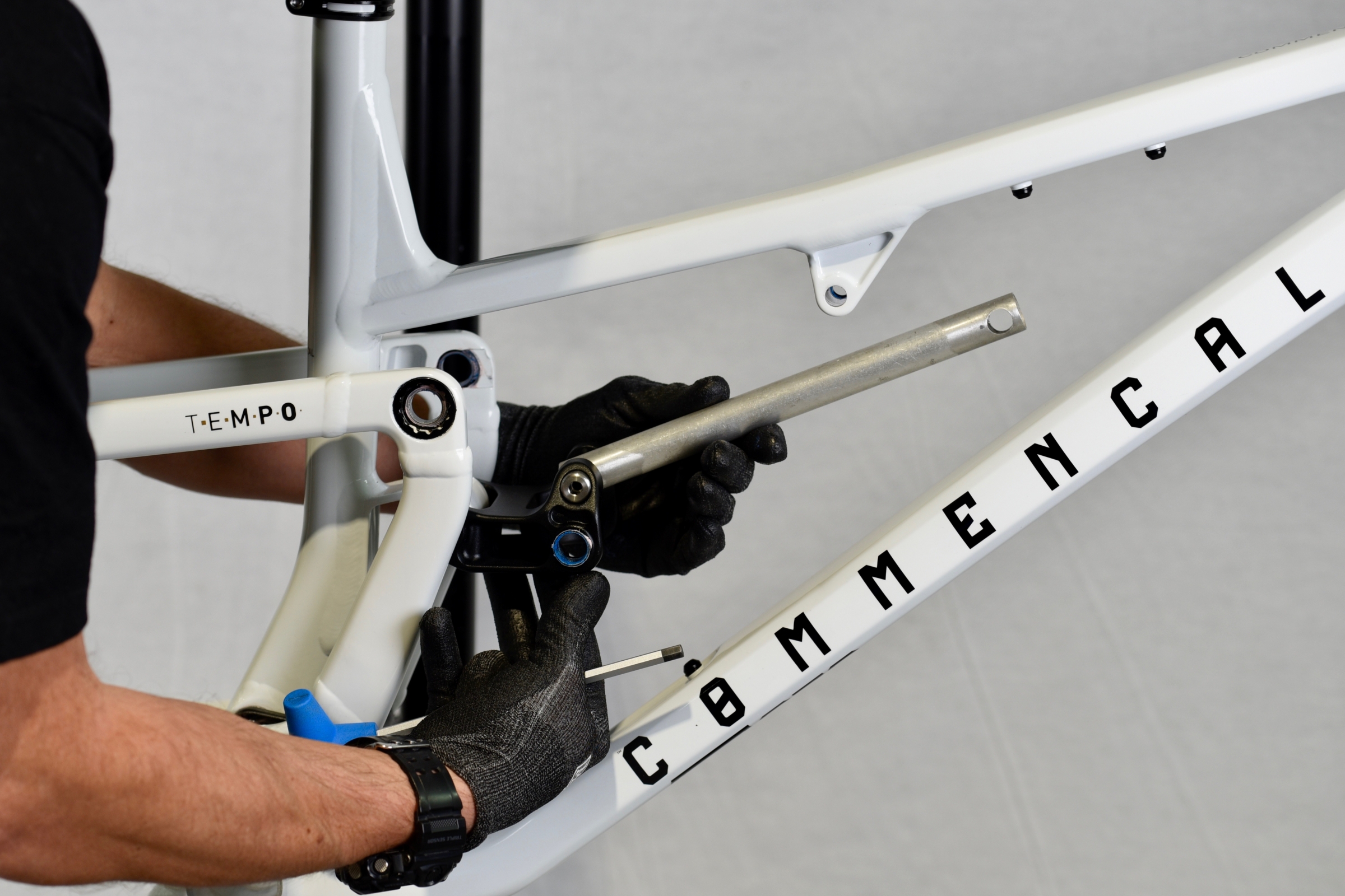
Now you can rotate the upper link forward and access the link/shock axle.
With a 6mm Allen key remove the upper link/shock axle.
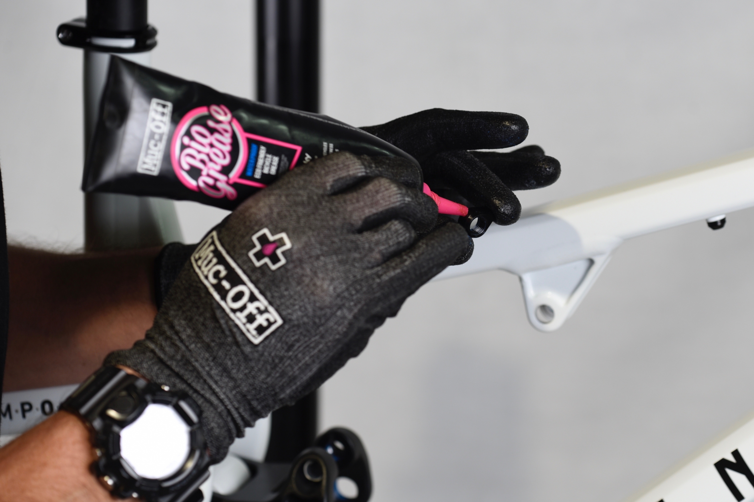
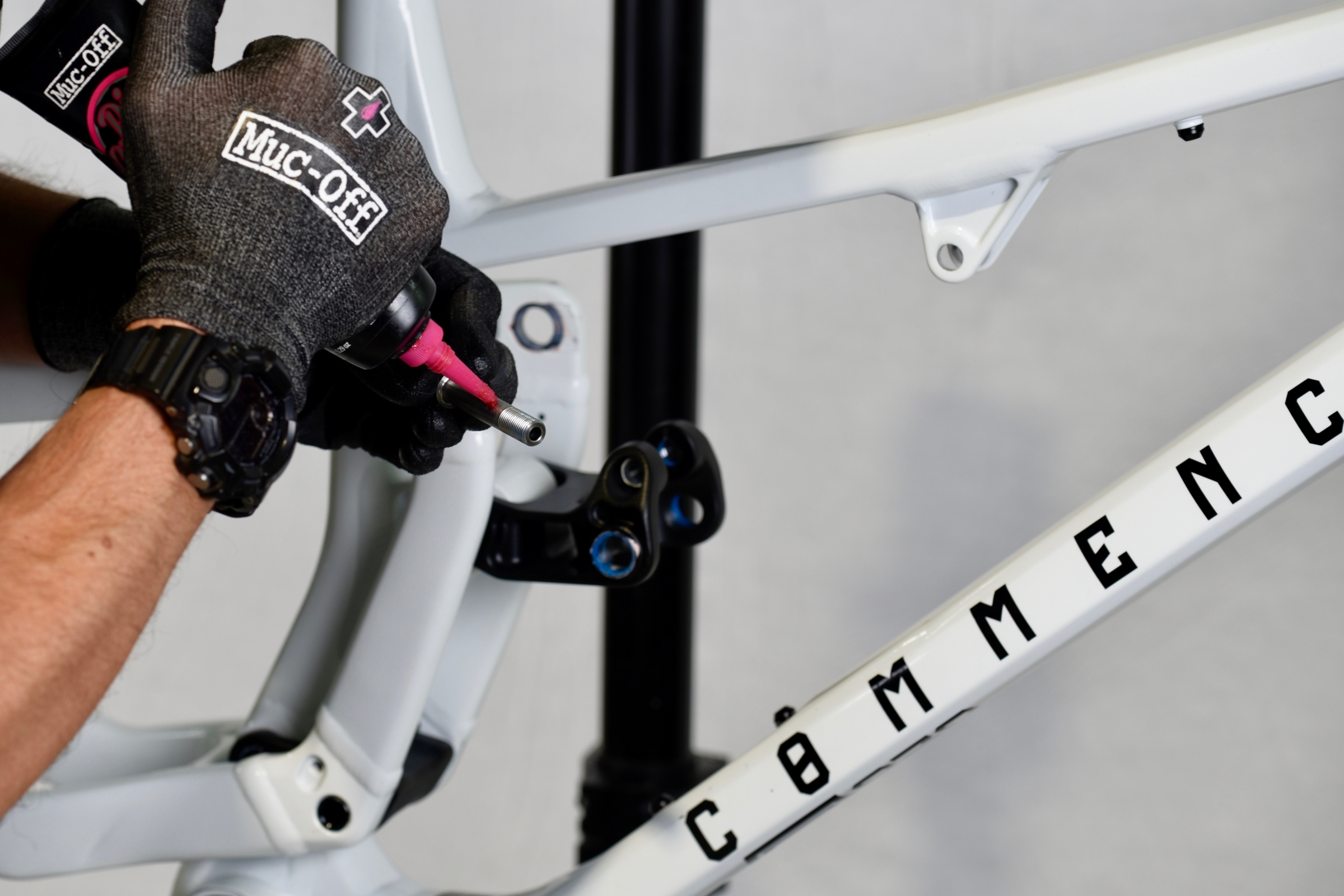
Remove front triangle/shock axle insert and grease the contact zone.
Grease upper link/shock axle. Do not grease the thread.
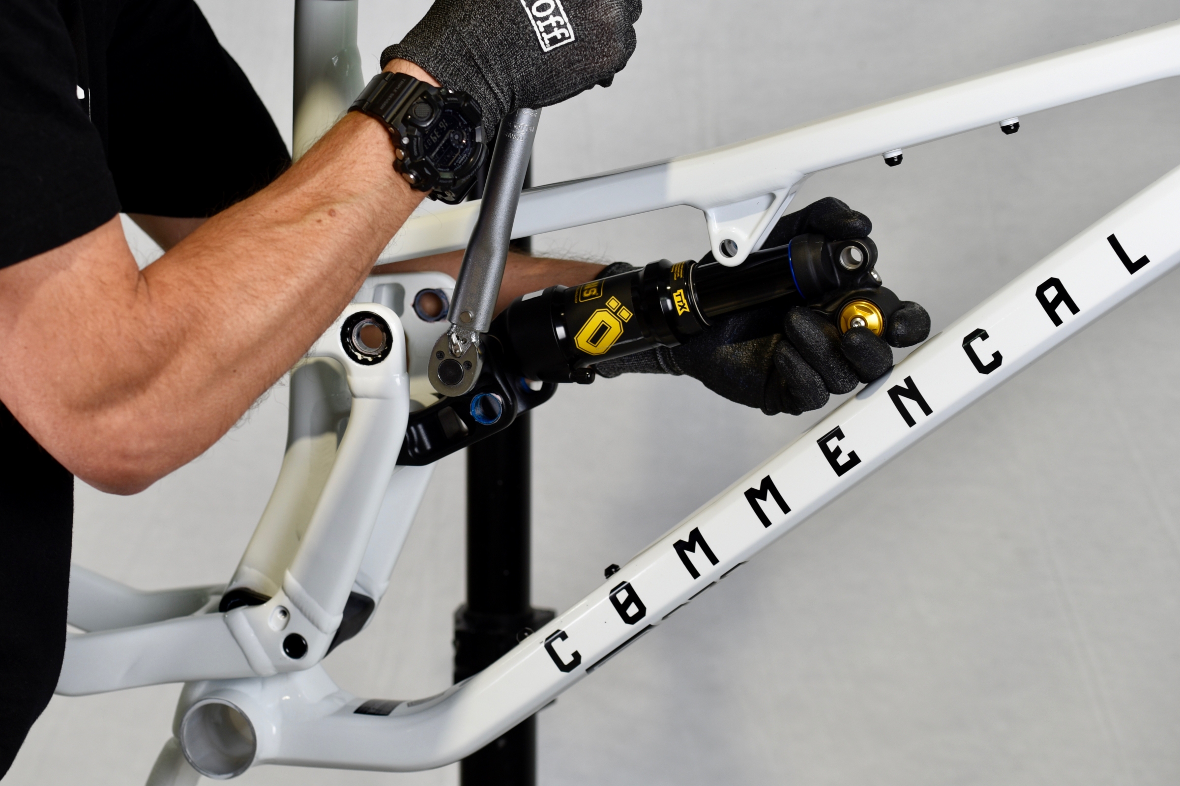
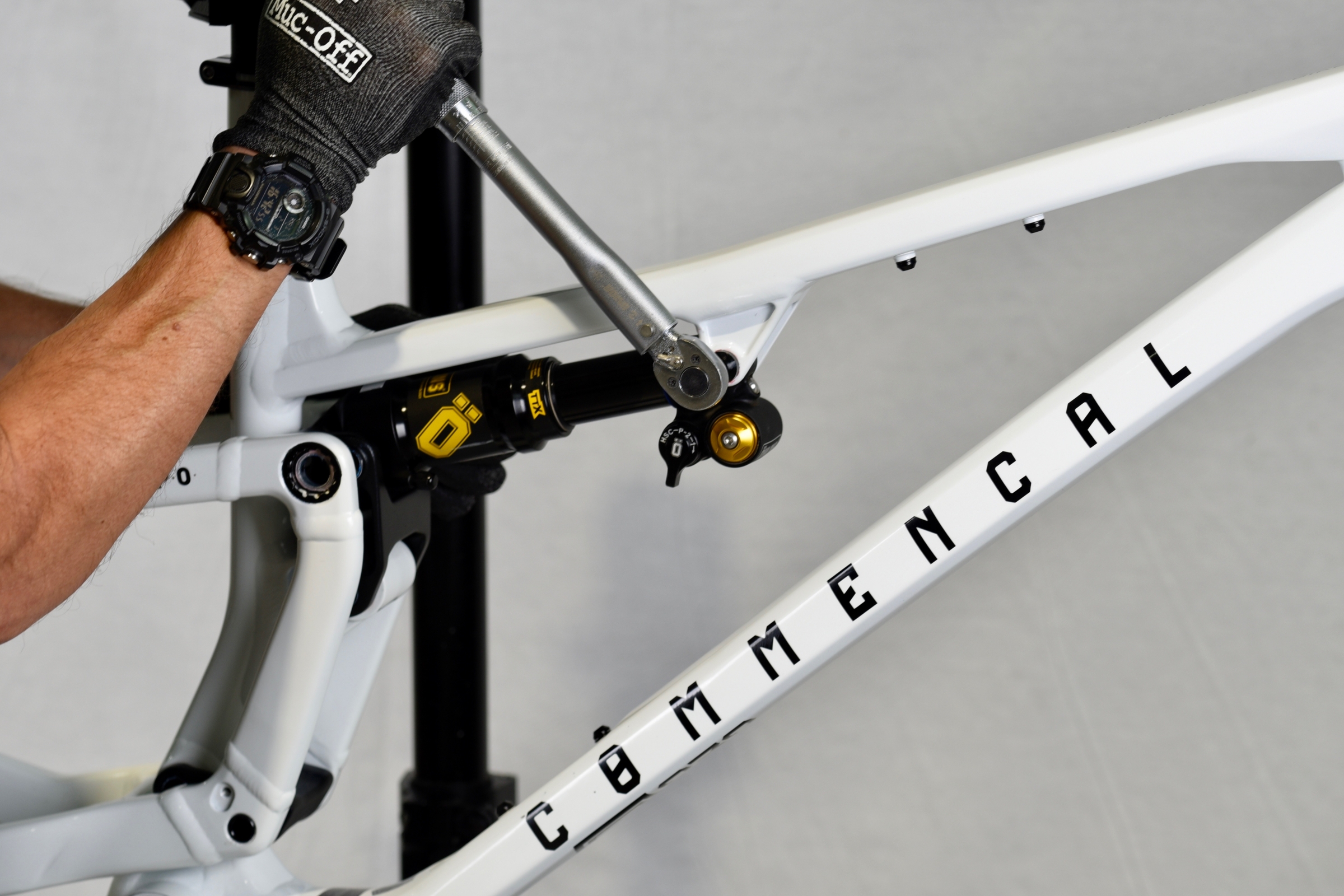
Place your shock in the upper link and install the axle, with a 6mm Allen key.
Torque the axle to 10N.m.
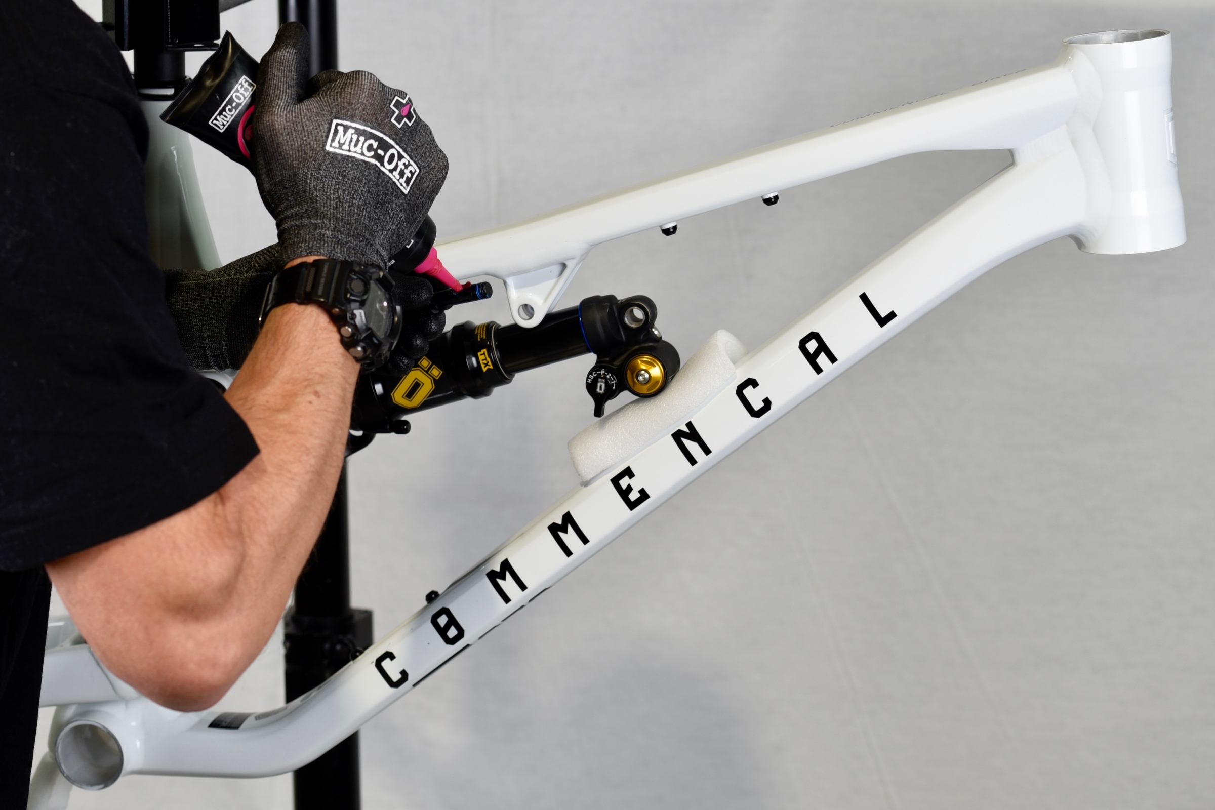
Grease front triangle/shock axle. Do not grease the thread.
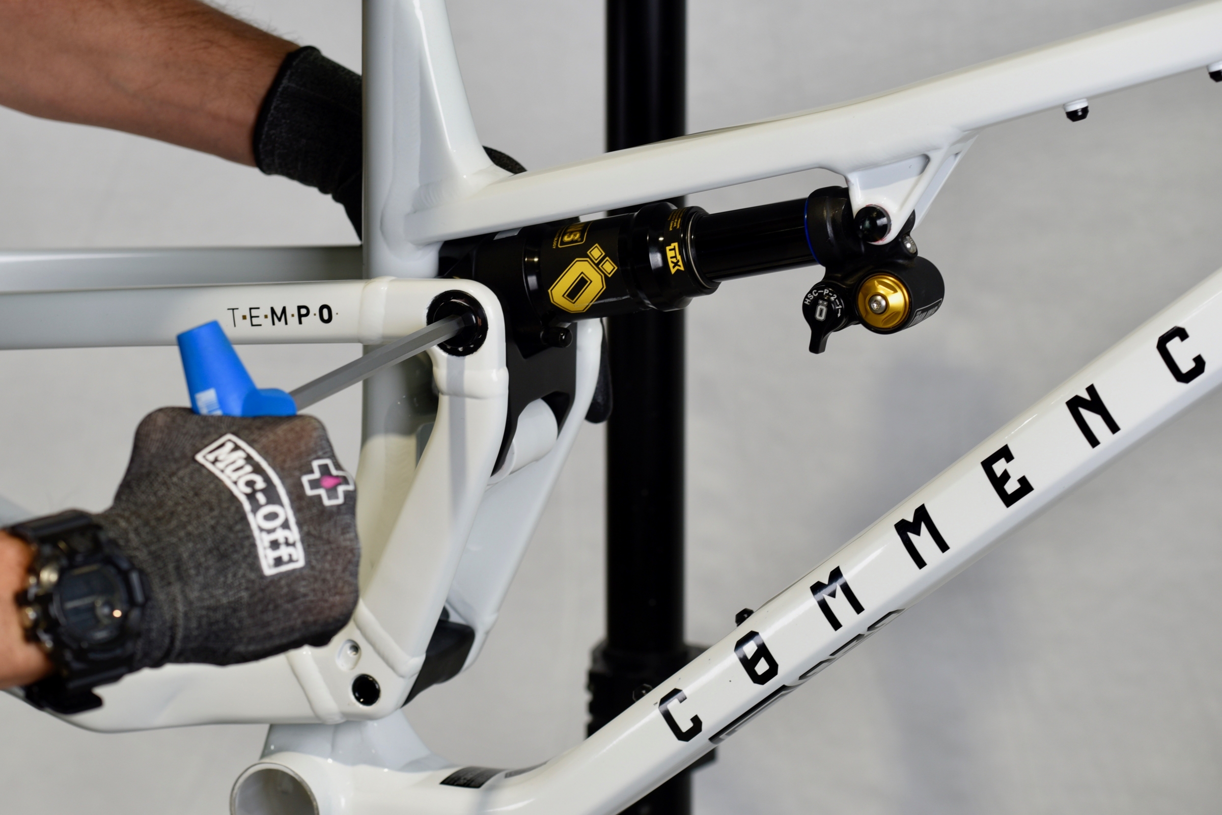
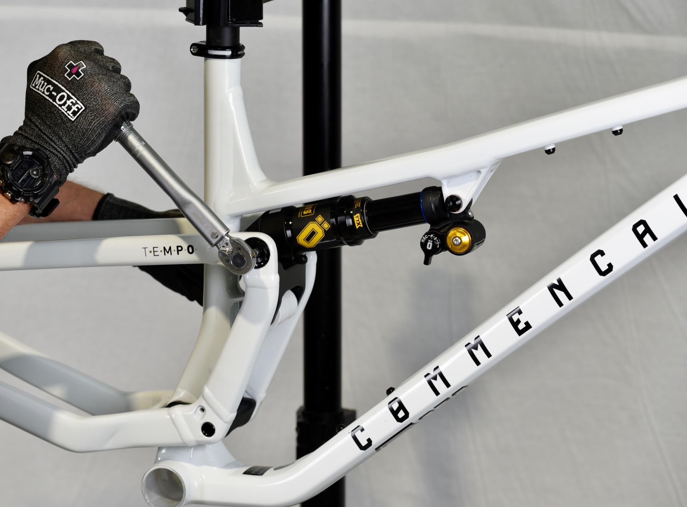
Rotate the upper link backwards to install the shock into the front triangle mount.
With a 6mm Allen key, install front triangle/shock axle.
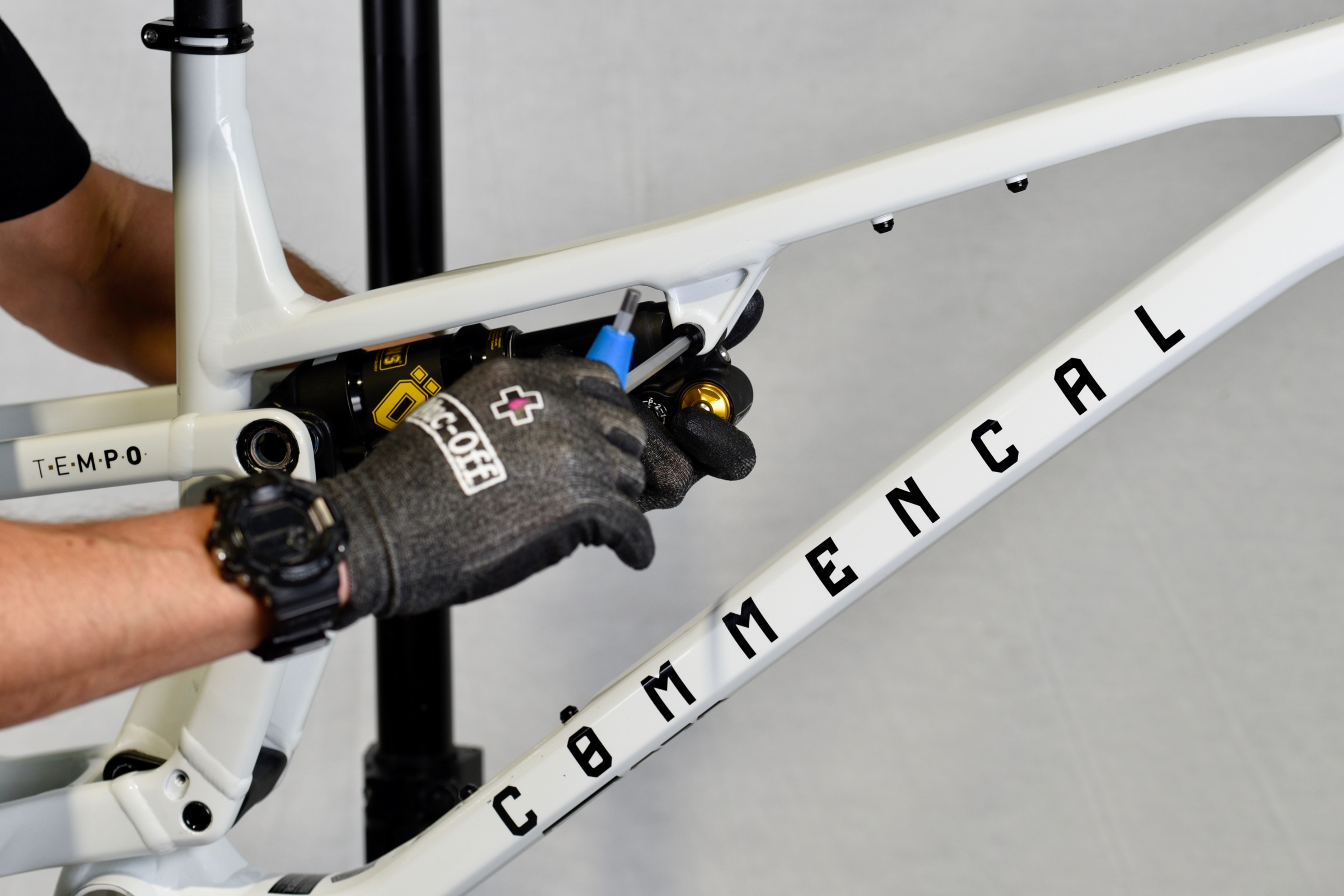
Torque the axle to 10N.m.
With an 8mm Allen key install the rear triangle/upper link axles.
Torque the axle to 12N.m.
Next step is to install the headset cups in the headtube.
Prepare your integrated cable routing headset.
And identify every parts, particularly upper and lower cup.
.jpg)
Grease the upper part of the head tube.
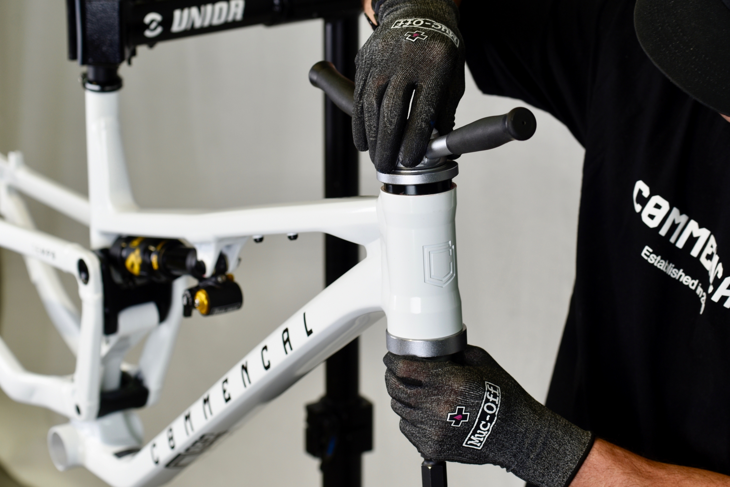
Install upper cup with a headset press.
Note: upper cup has a thinner bearing than lower cup. Make sure to install the correct one.
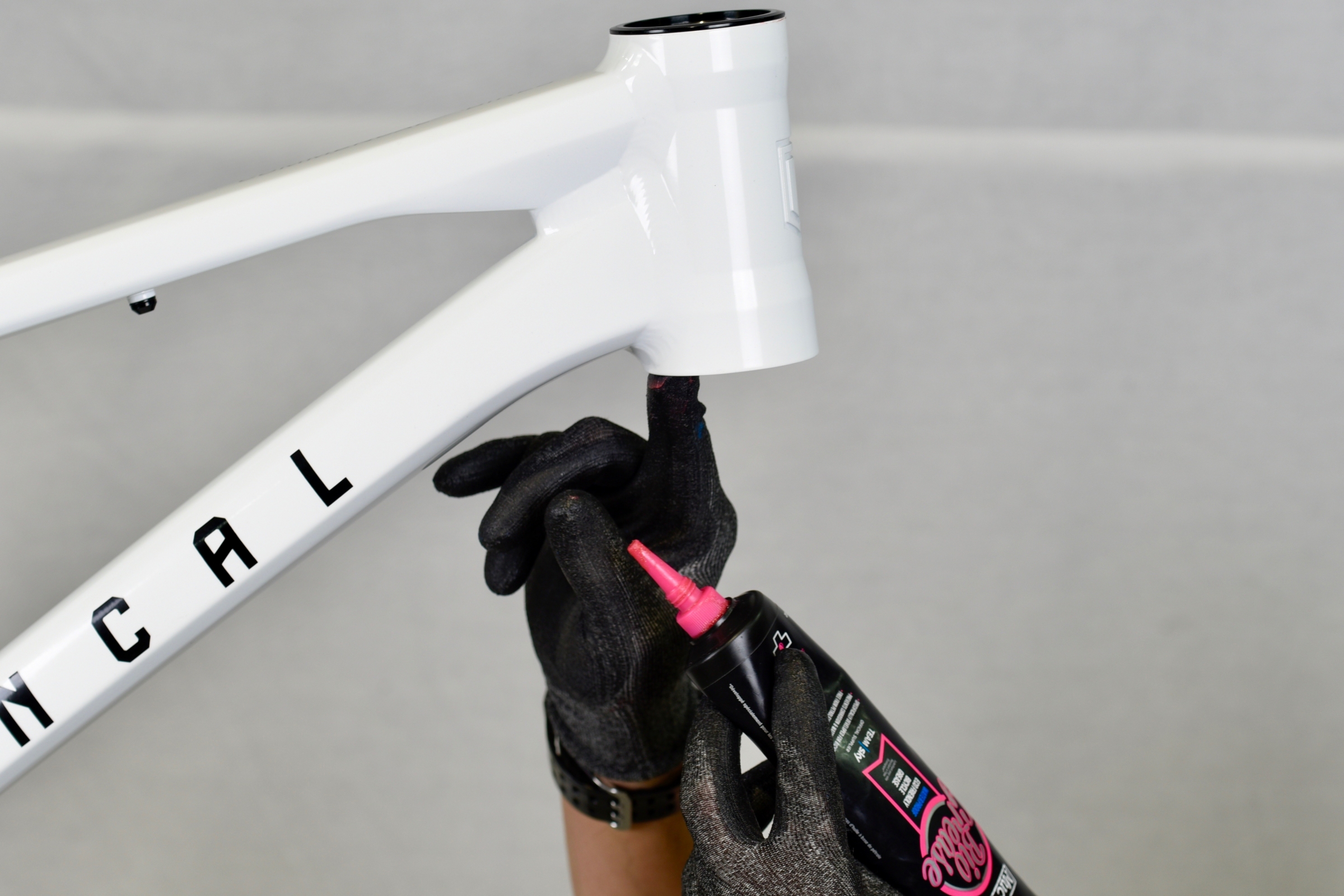
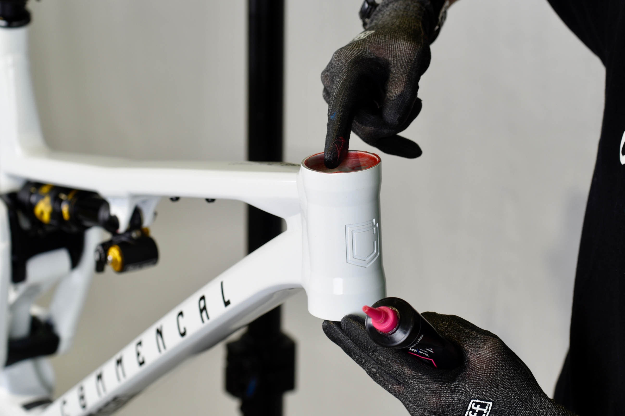
Grease the lower part of the head tube.
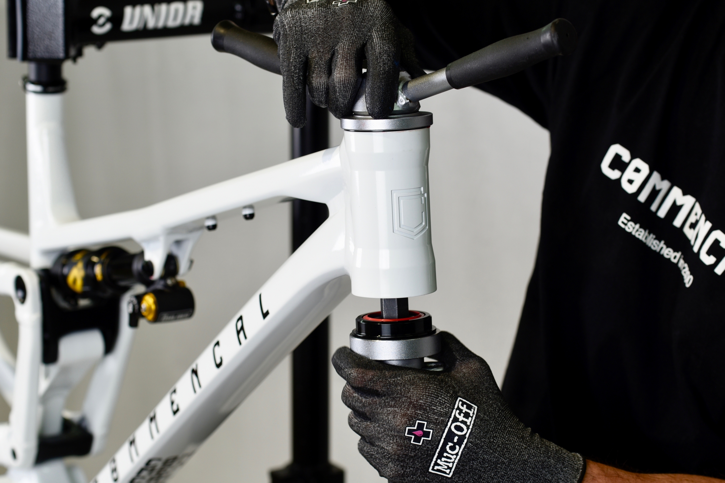
Install lower cup with a headset press.
Note: lower cup has a red internal seal.
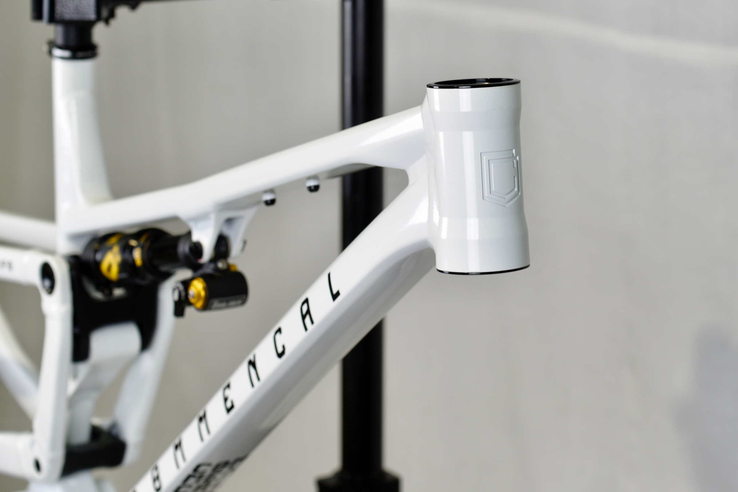
Now your headset cups are installed in the head tube.
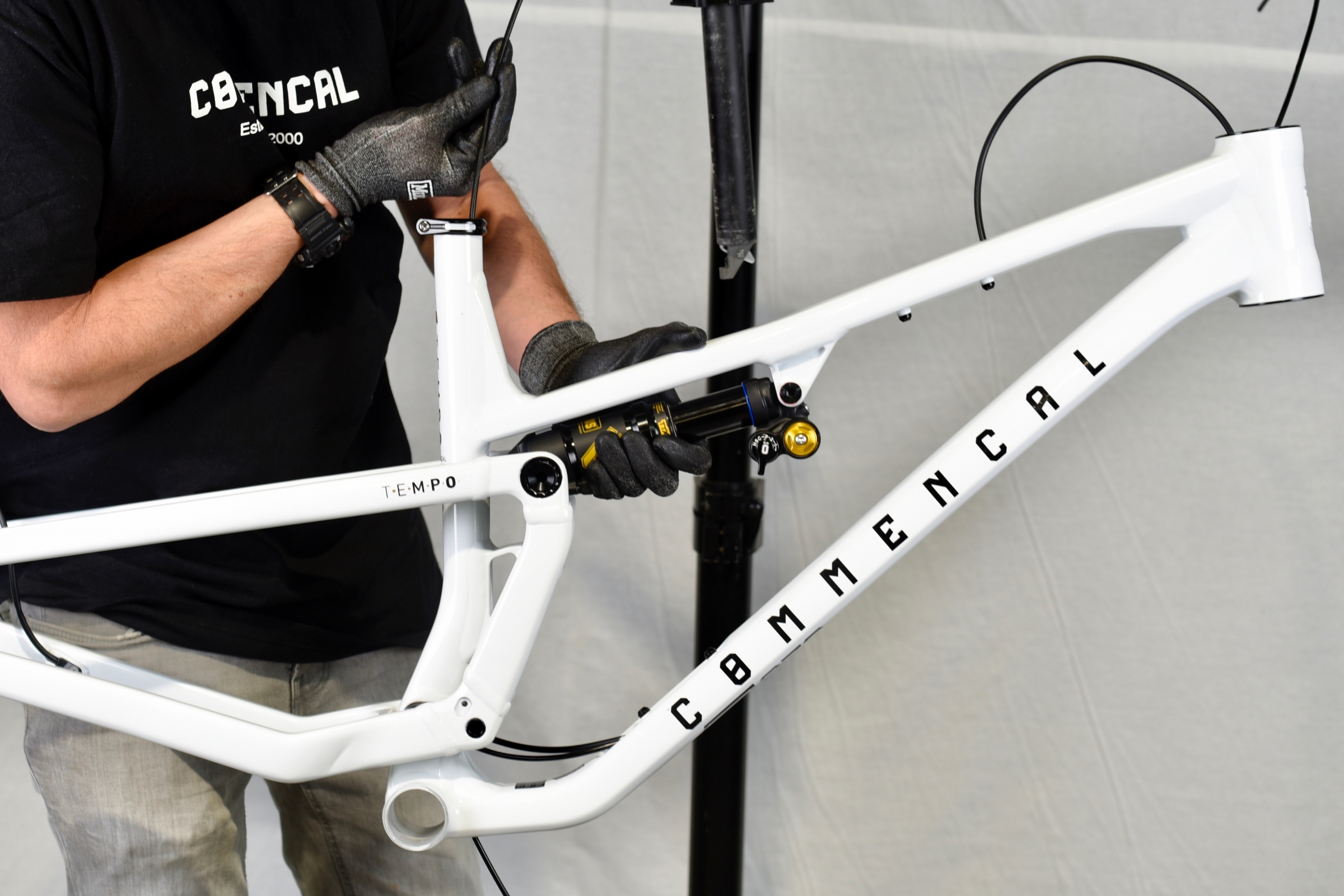
Next step is to route the derailleur housing inside the frame.
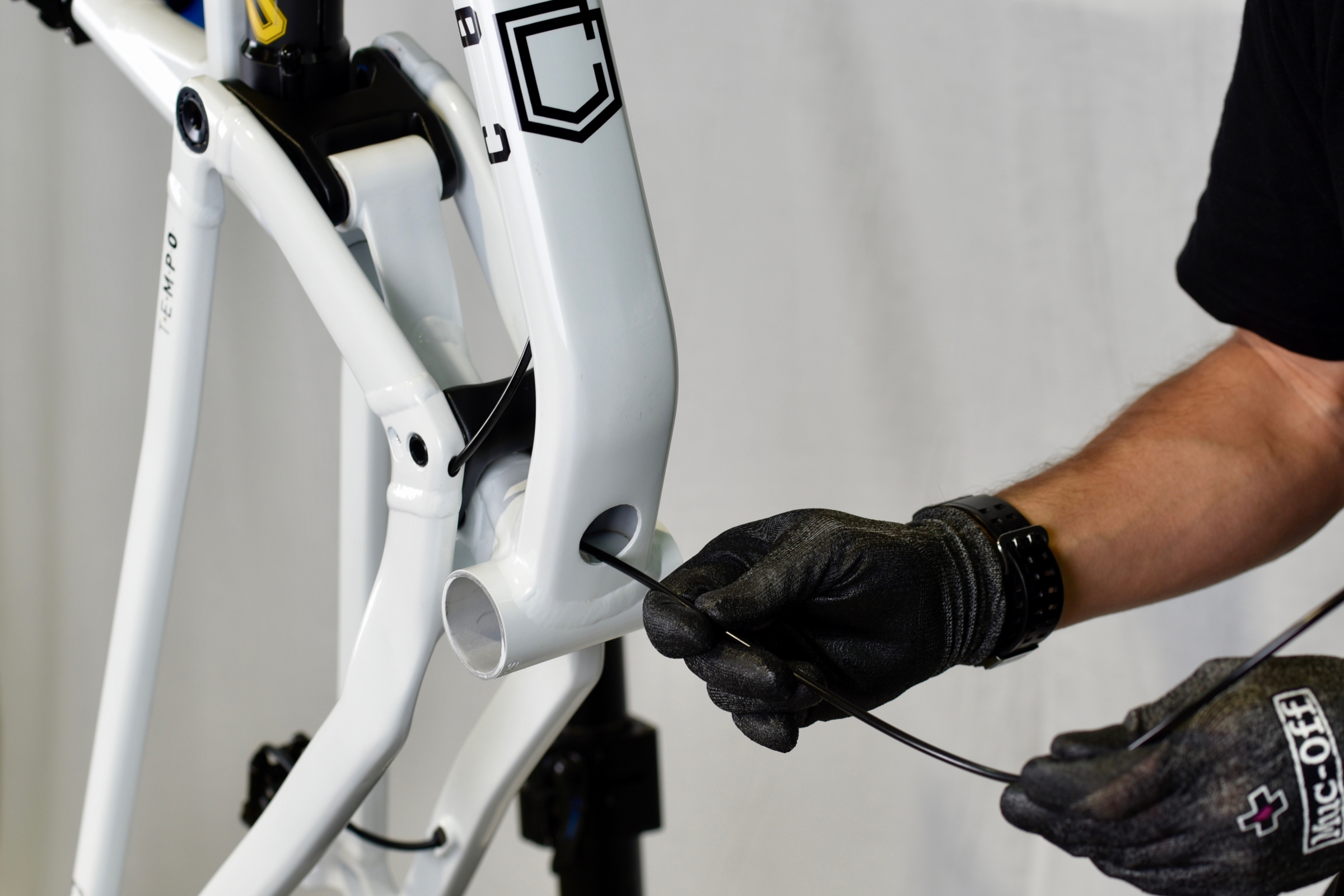
Use a brand-new inner cable and route it into the right chain stay from front to back.
The inner cable must come out of the chain stay via the hole next to the hanger.
Use that inner cable as a guide to route the housing from the back of the chain stay.
The housing will come out of the chain stay at bottom bracket level.
You can now remove the inner cable.
Route the housing into the down tube and up to the head tube.
Your housing is now routed properly through the frame.
Tip: Use a piece of tape at the end of the housing, on headset side, to identify it as the derailleur one.
Next step is routing the rear brake hose inside the frame.
Install brake caliper onto the brake mount with a 5mm Allen key.
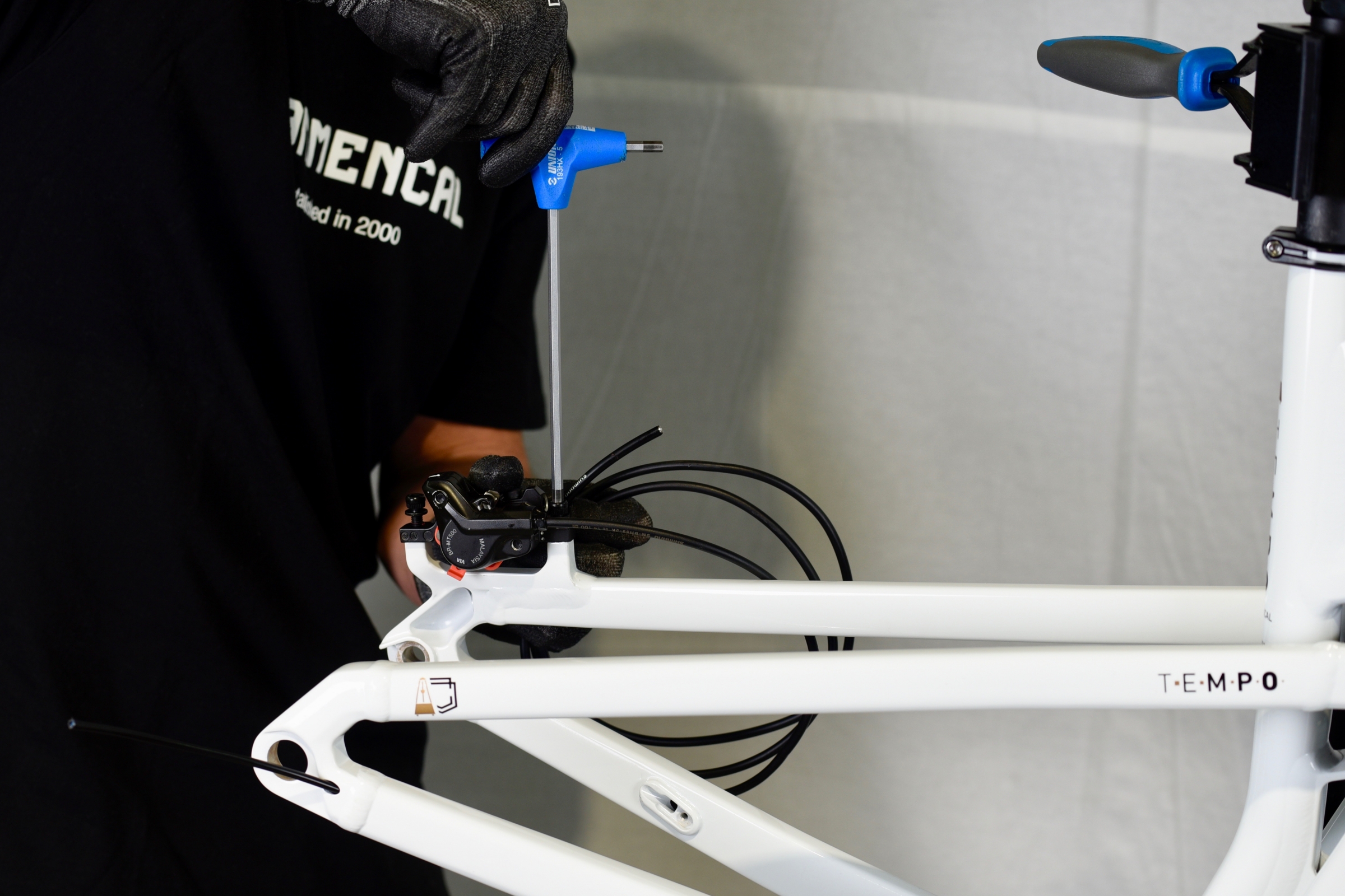
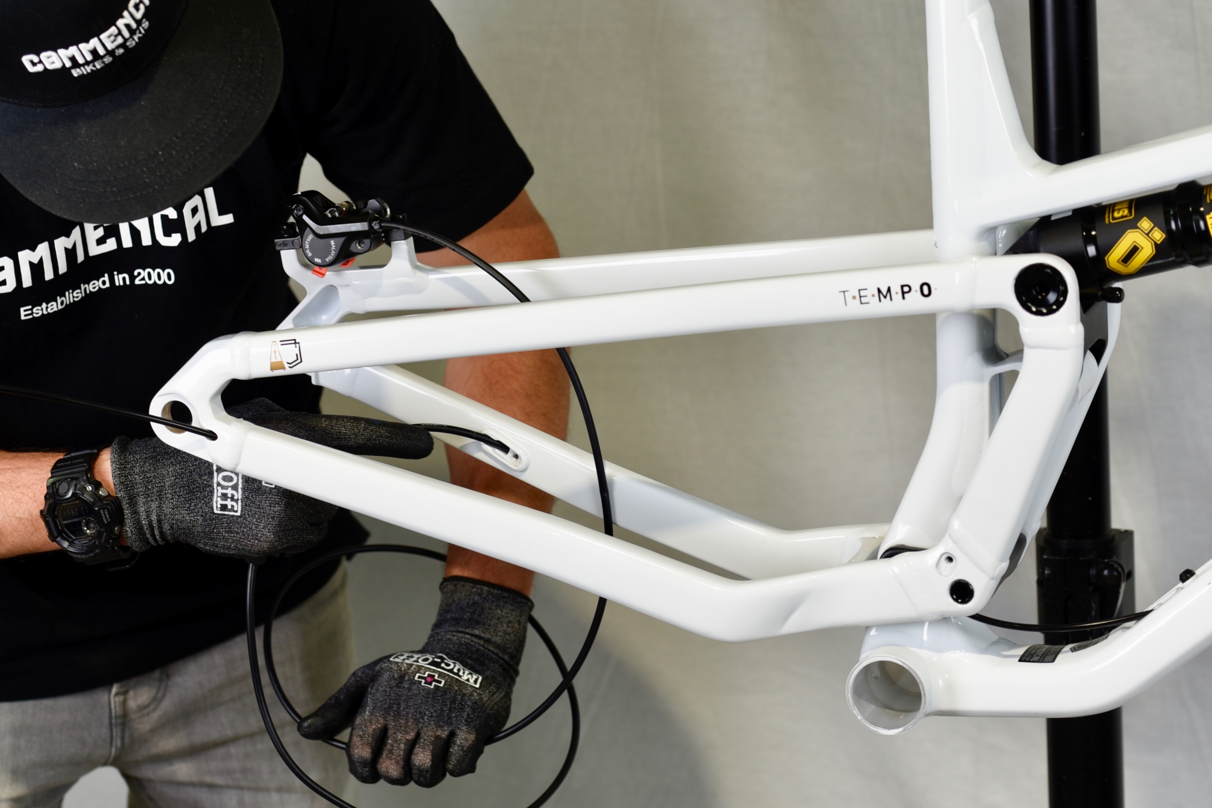
Route the brake hose into the left chain stay from back to front.
Next, route the brake hose into the down tube, up to the head tube.
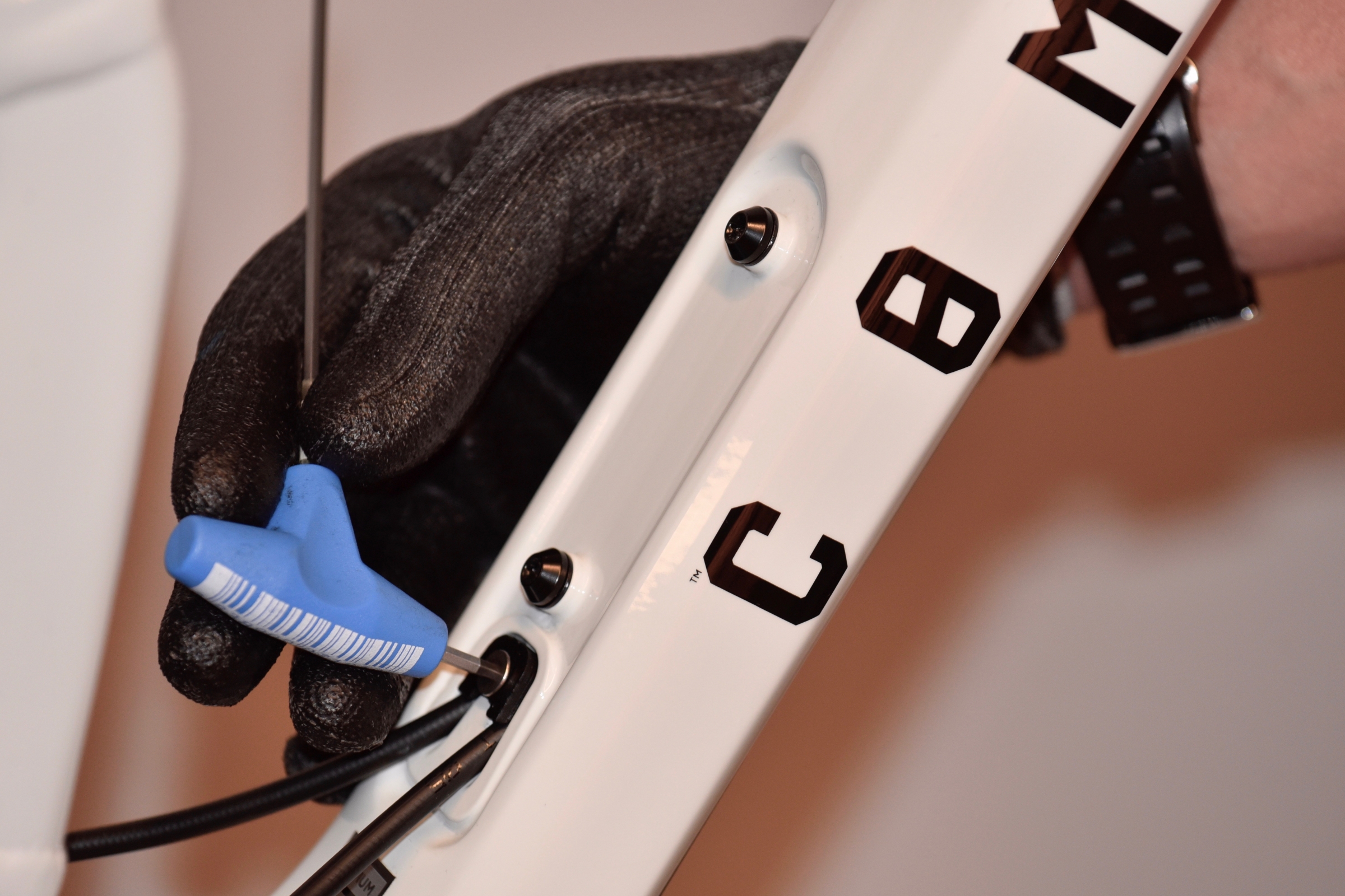
Position cable guide onto the down tube and tighten the bolt with a 2.5mm Allen key.
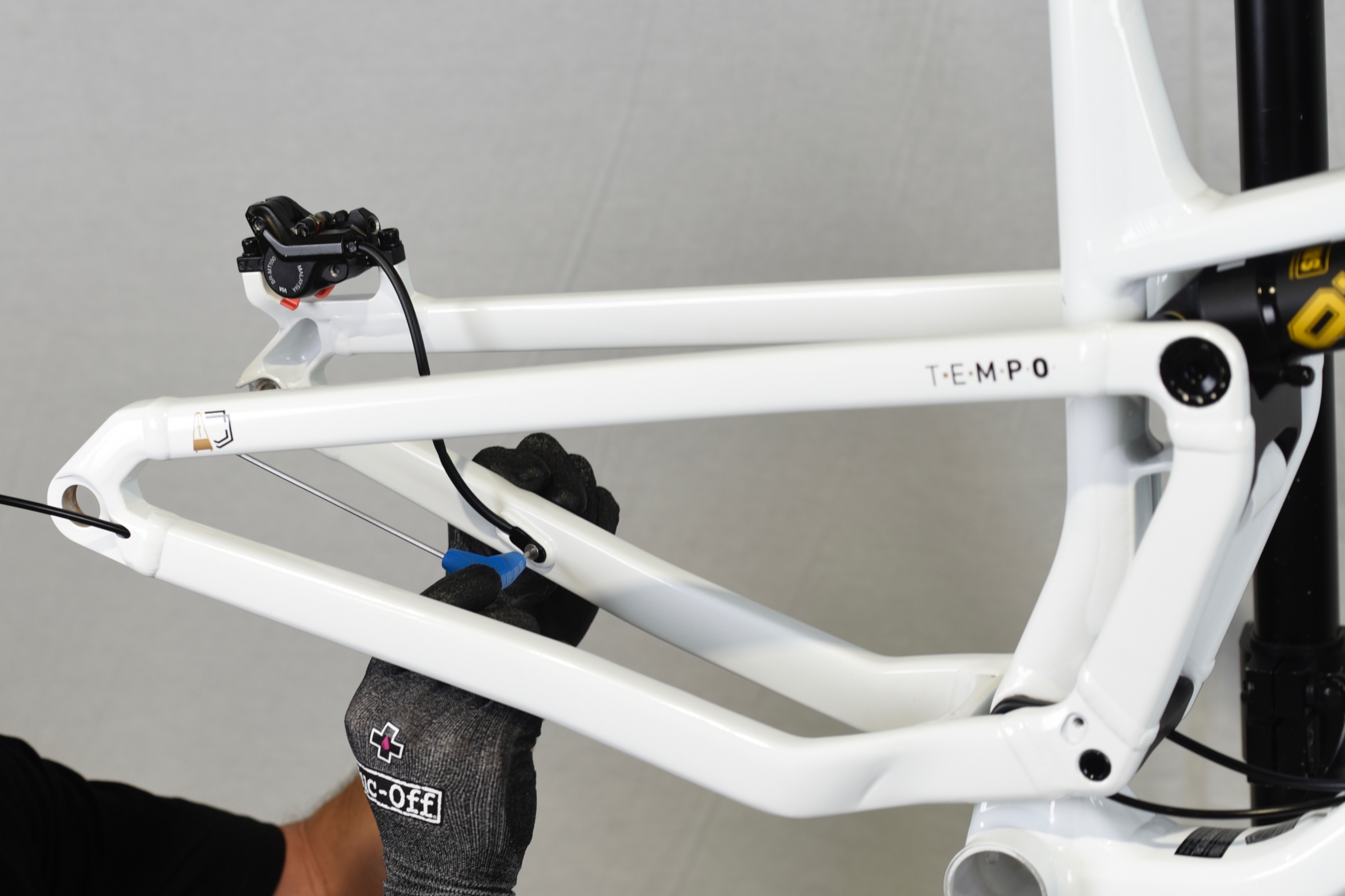
Adjust housing lenght to avoid excess tension while suspension is operating.
Position cable guide onto the chain stay and tighten the bolt with a 2.5mm Allen key.
Next step is to route the dropper post housing inside the frame.
We recommend the following housing lengths, depending on frame size:
1300mm on S and M
1350mm on L
1400mm on XL
Route housing from the hole at the bottom of the down tube up to the seat tube.
Dropper post housing will come out of the top of the seat tube.
Now, route dropper post housing into the down tube, up to the head tube, by pushing it through the hole at bottom of down tube.
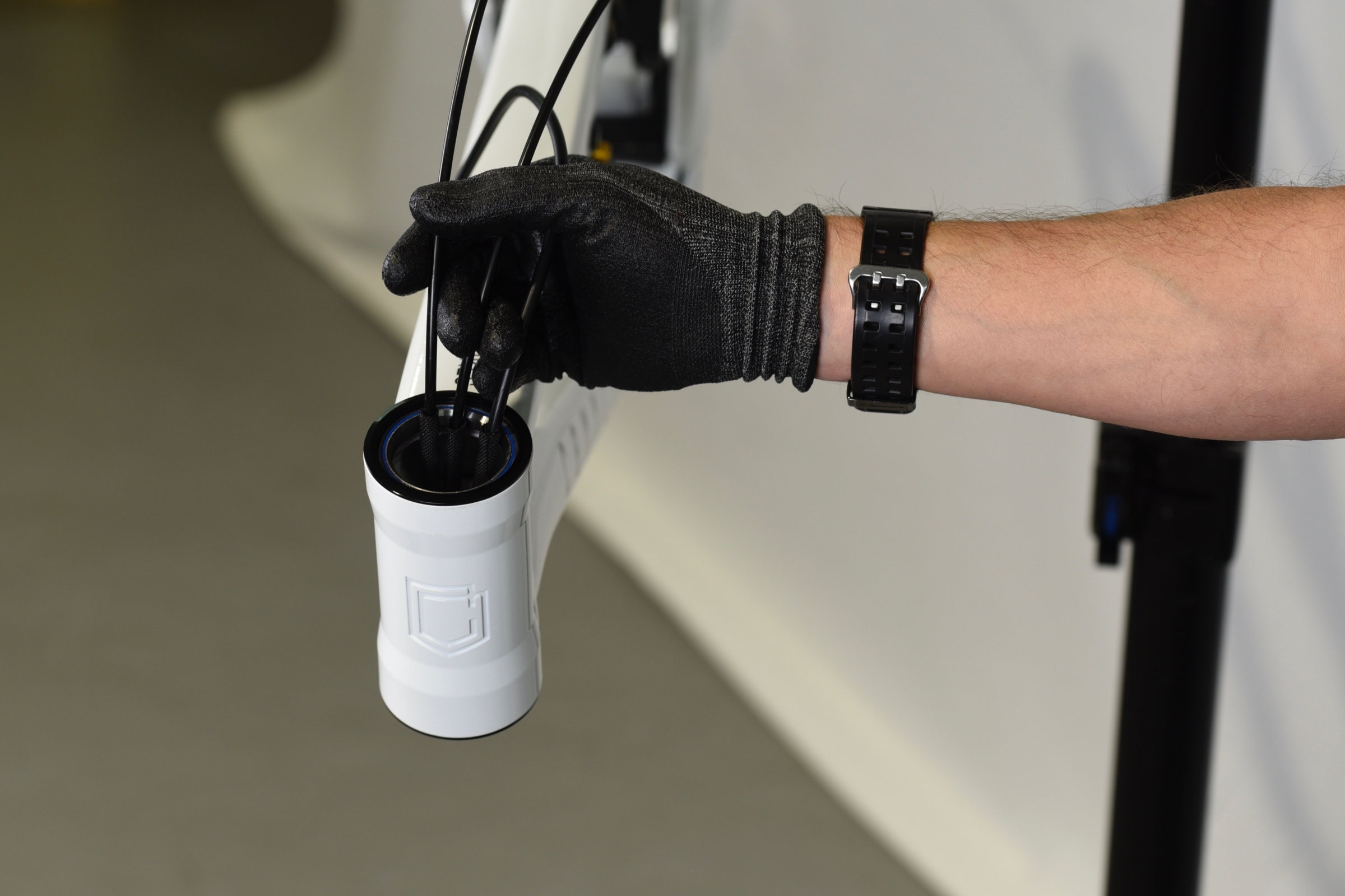
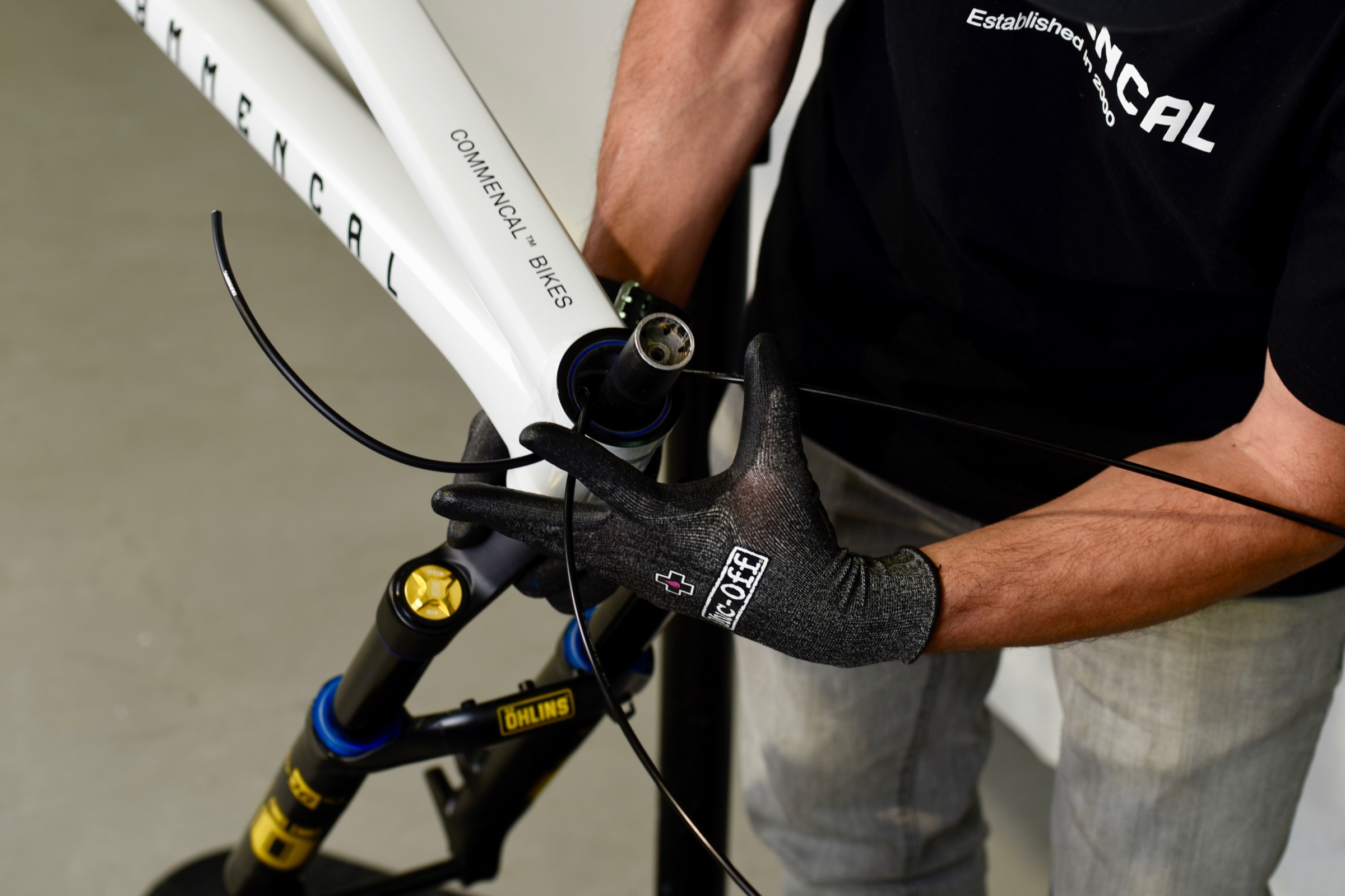
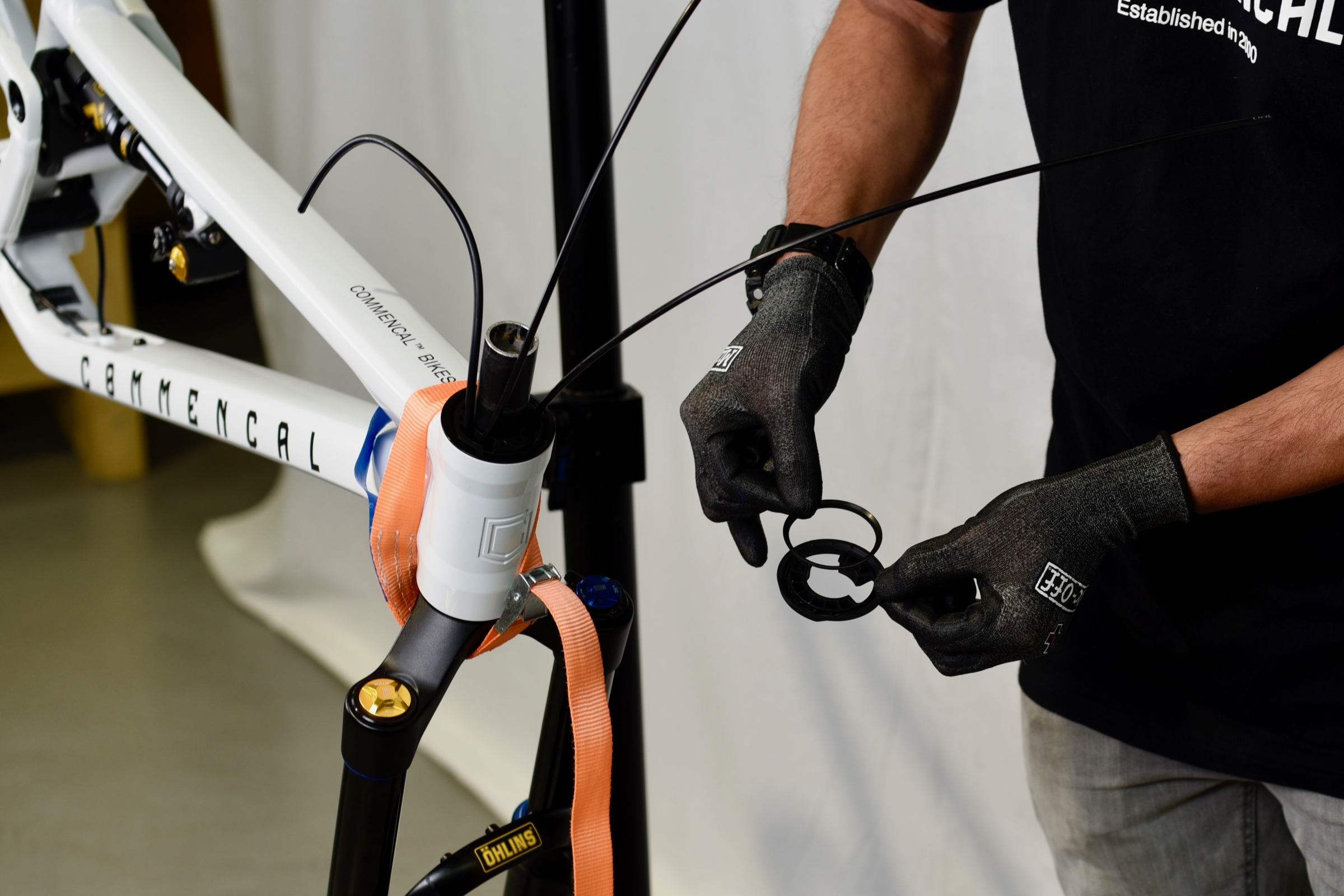
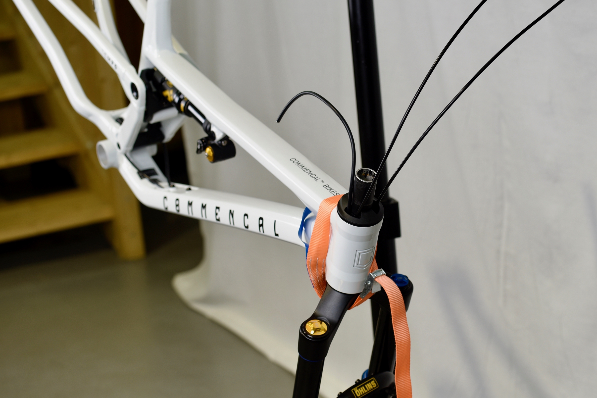
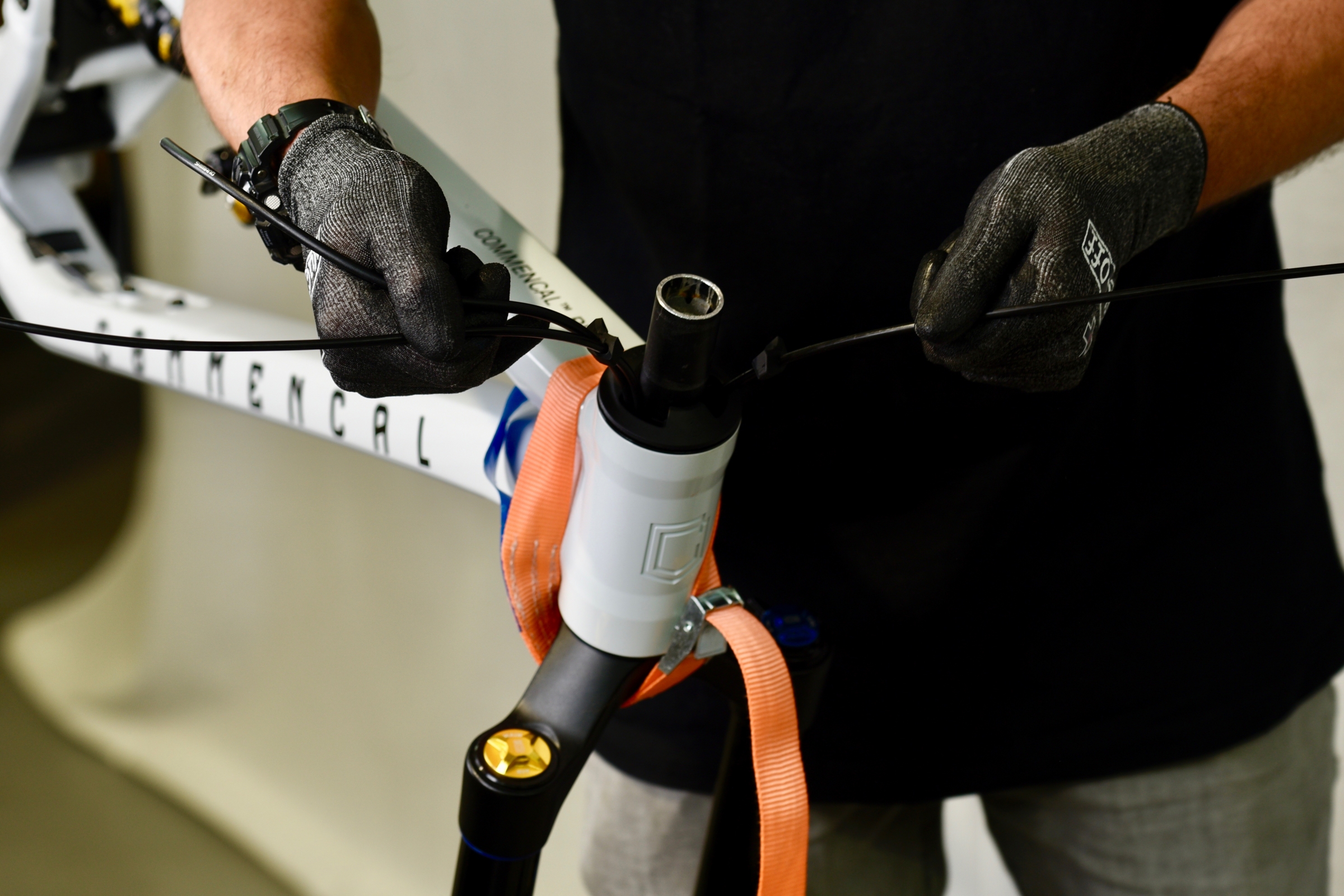
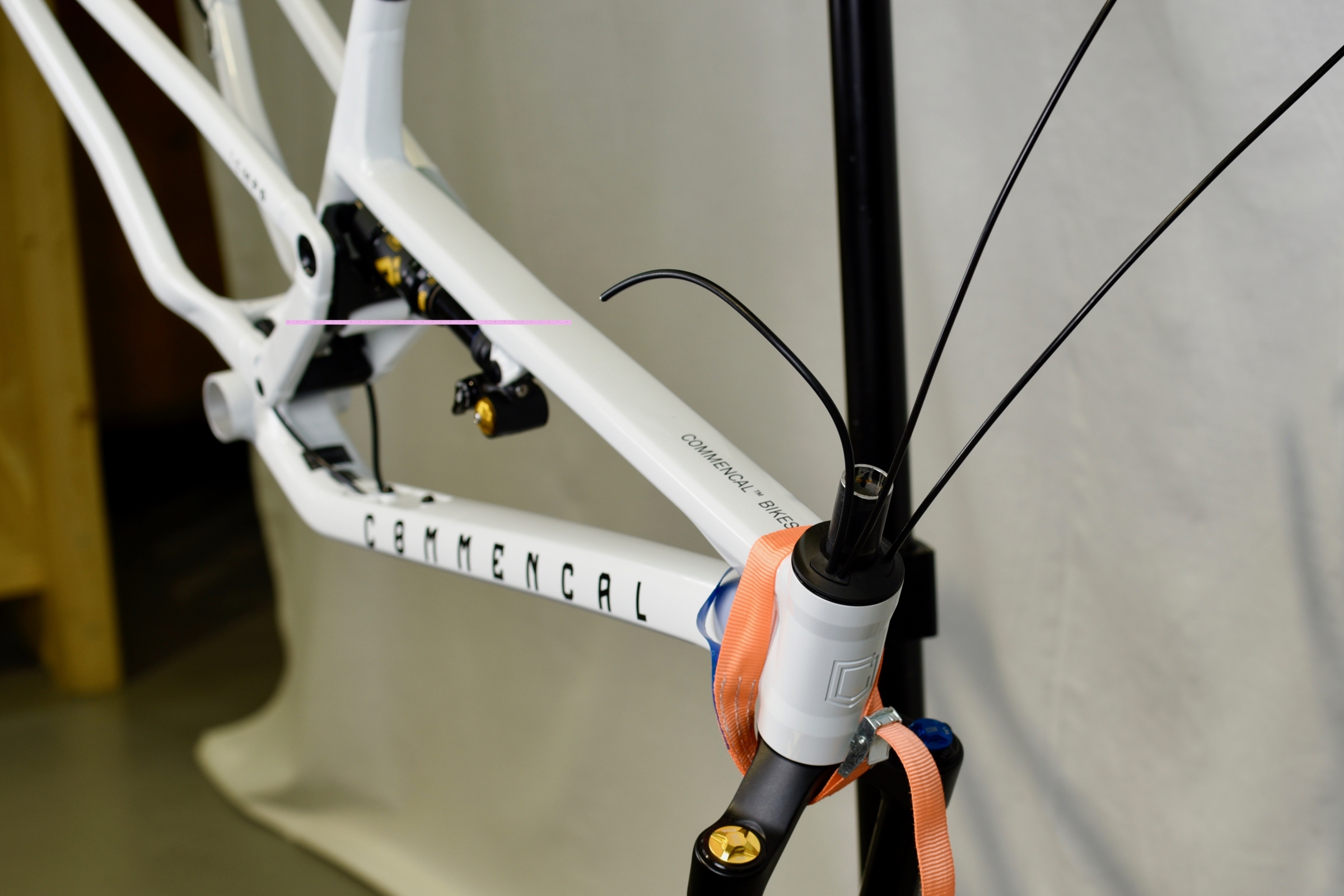
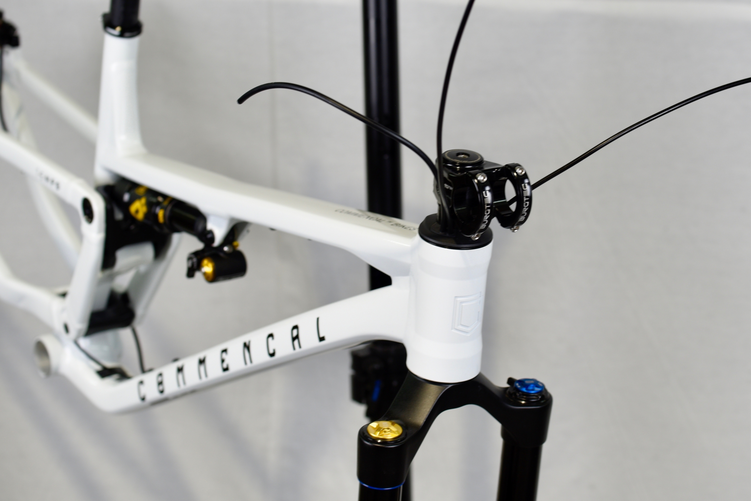
Your derailleur, brake and dropper housing should now be coming out of the head tube. Put foam tubes around each housing to avoid any rattling noise inside the down tube.
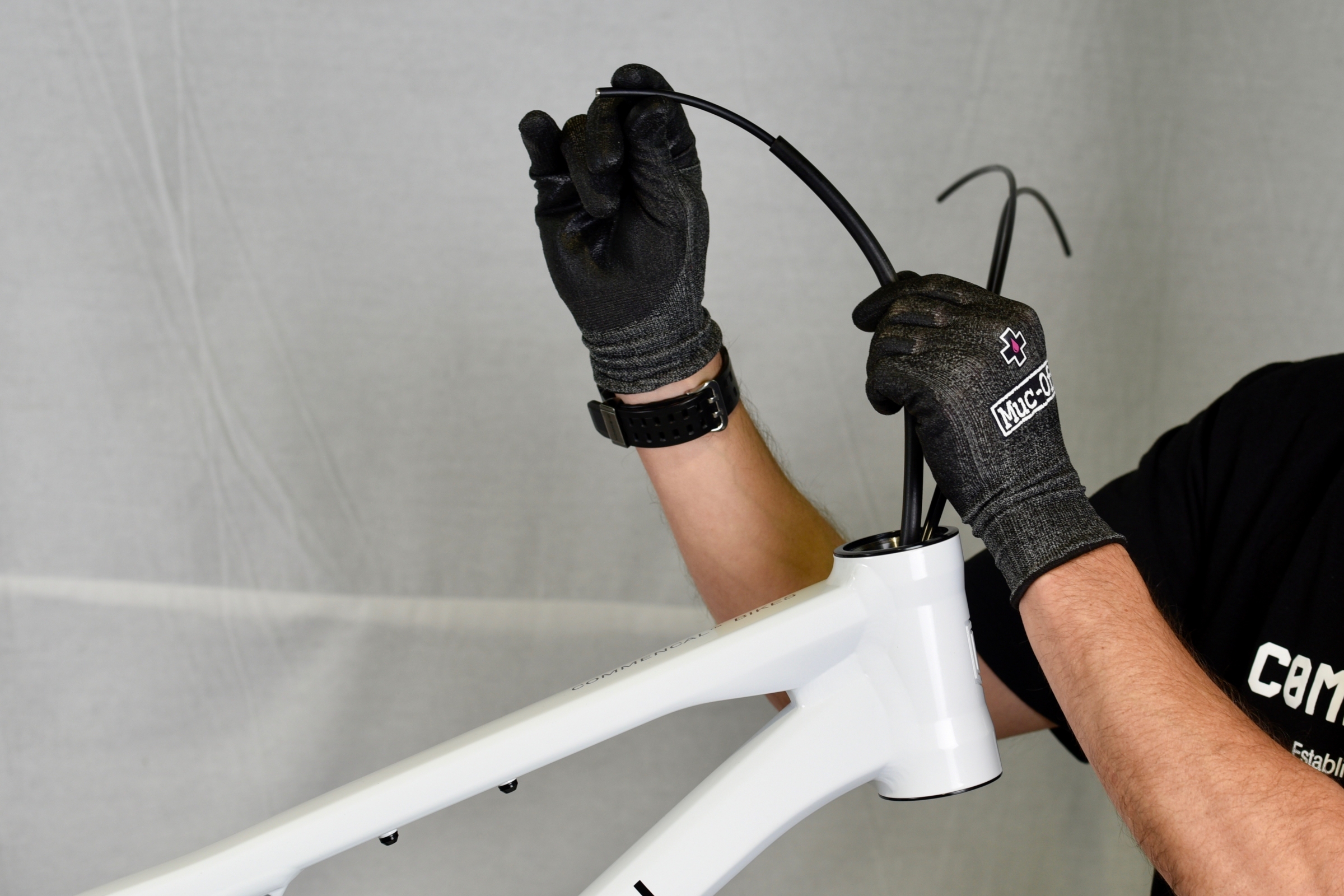
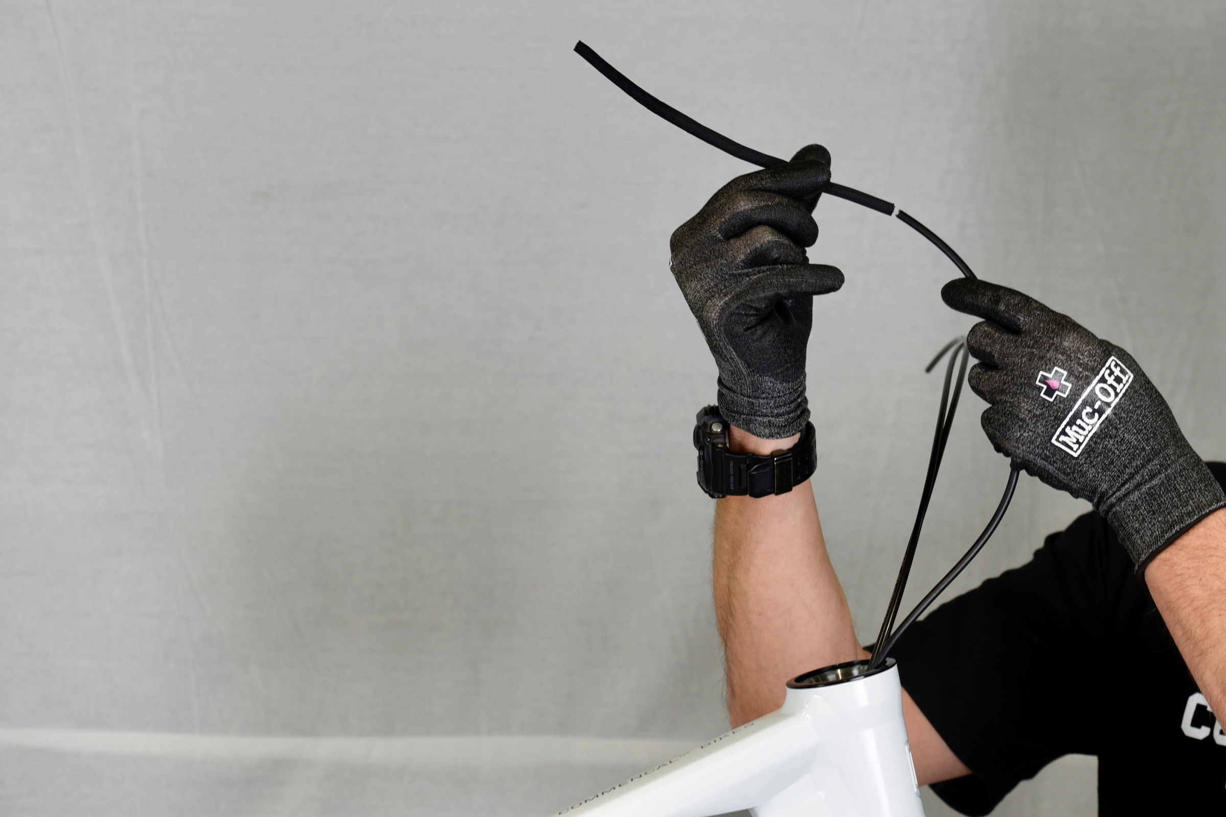
Place nylon tubes on each housing to avoid any rubbing on the steerer.
Nylon tubes should be placed at upper bearing level to protect the steerer without making contact with the headset compression ring.
Next step is to install the fork to the frame.
We recommend the following fork steerer lengths, depending on frame size. And based on an assembly with a 40mm stem stack height, and 15mm of spacers ( 3x5mm ) :
Small size frame: 180mm fork steerer
Medium size frame: 185mm fork steerer
Large size frame: 190mm fork steerer
X-Large size frame: 195mm fork steerer
Make sure to cut your steerer at the correct length, according to your setup.
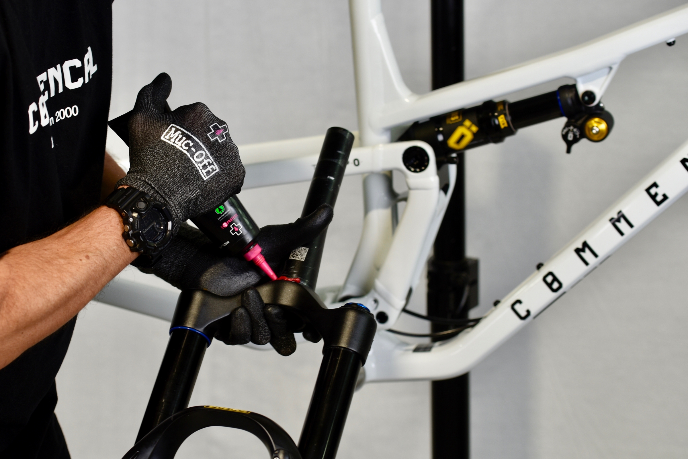
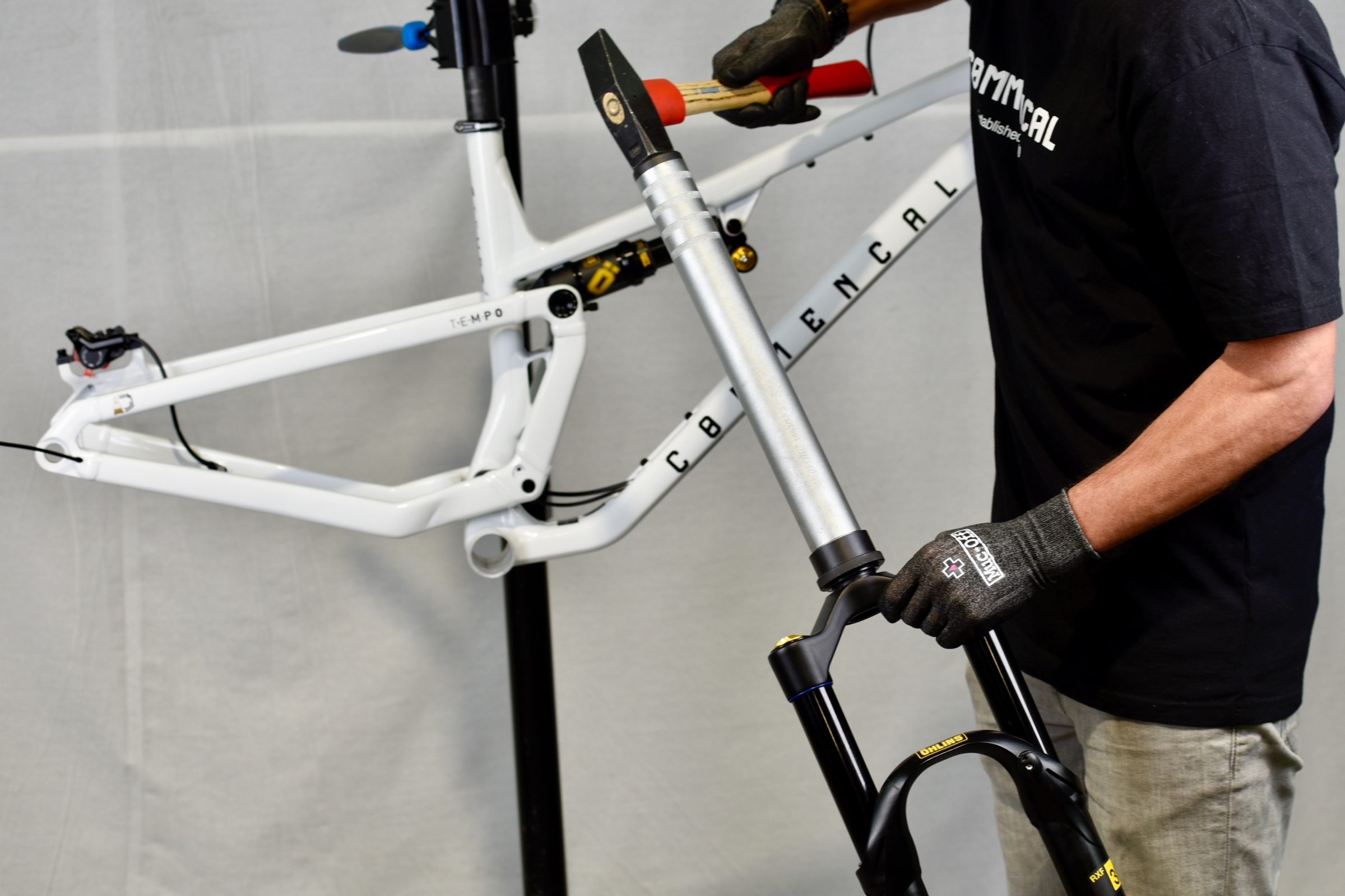
Grease steerer/crown race contact zone.
Install crown race with a crown race setter and a hammer.
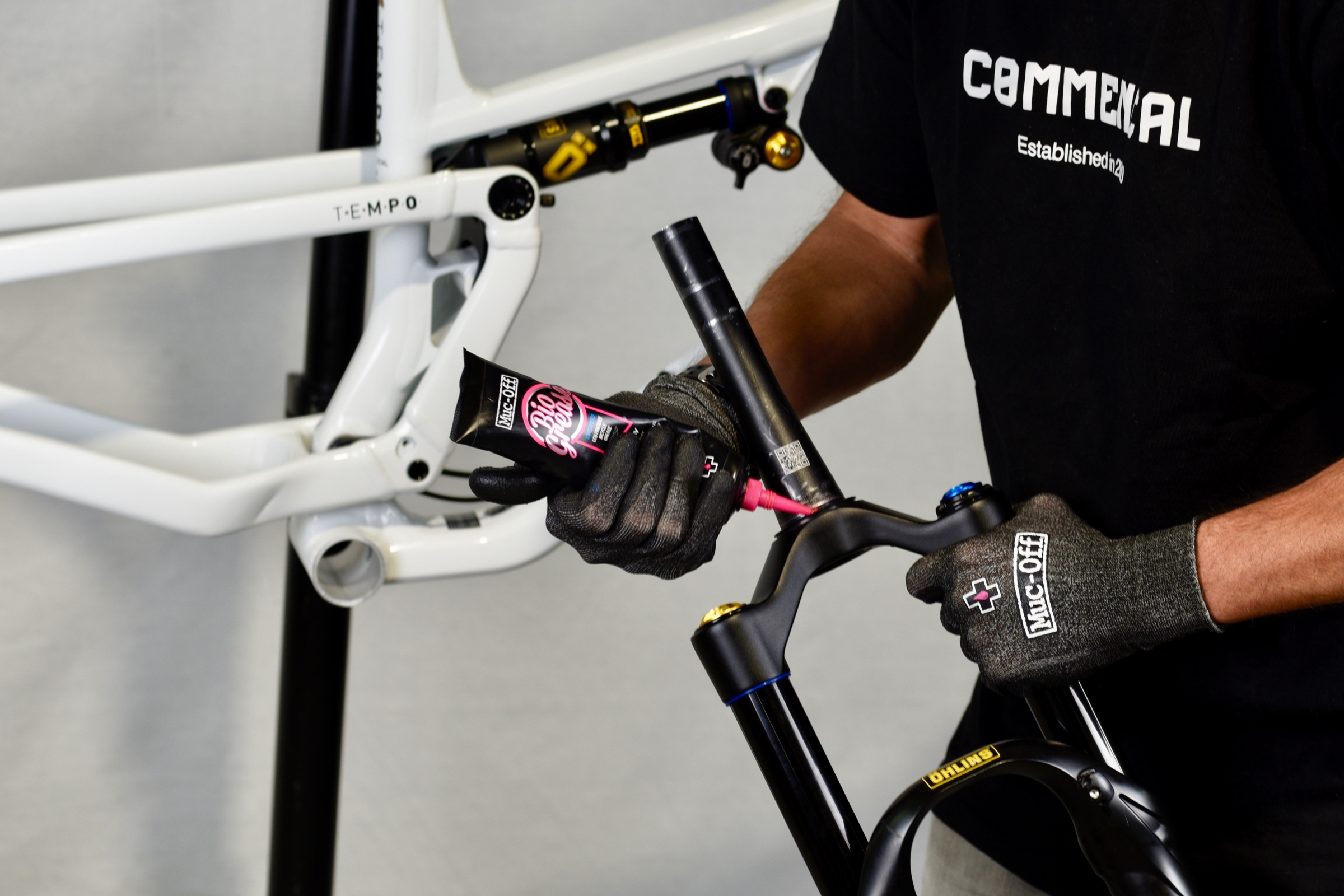
Grease crown race/lower bearing contact zone.
Now install fork into the head tube.
Make sure you place:
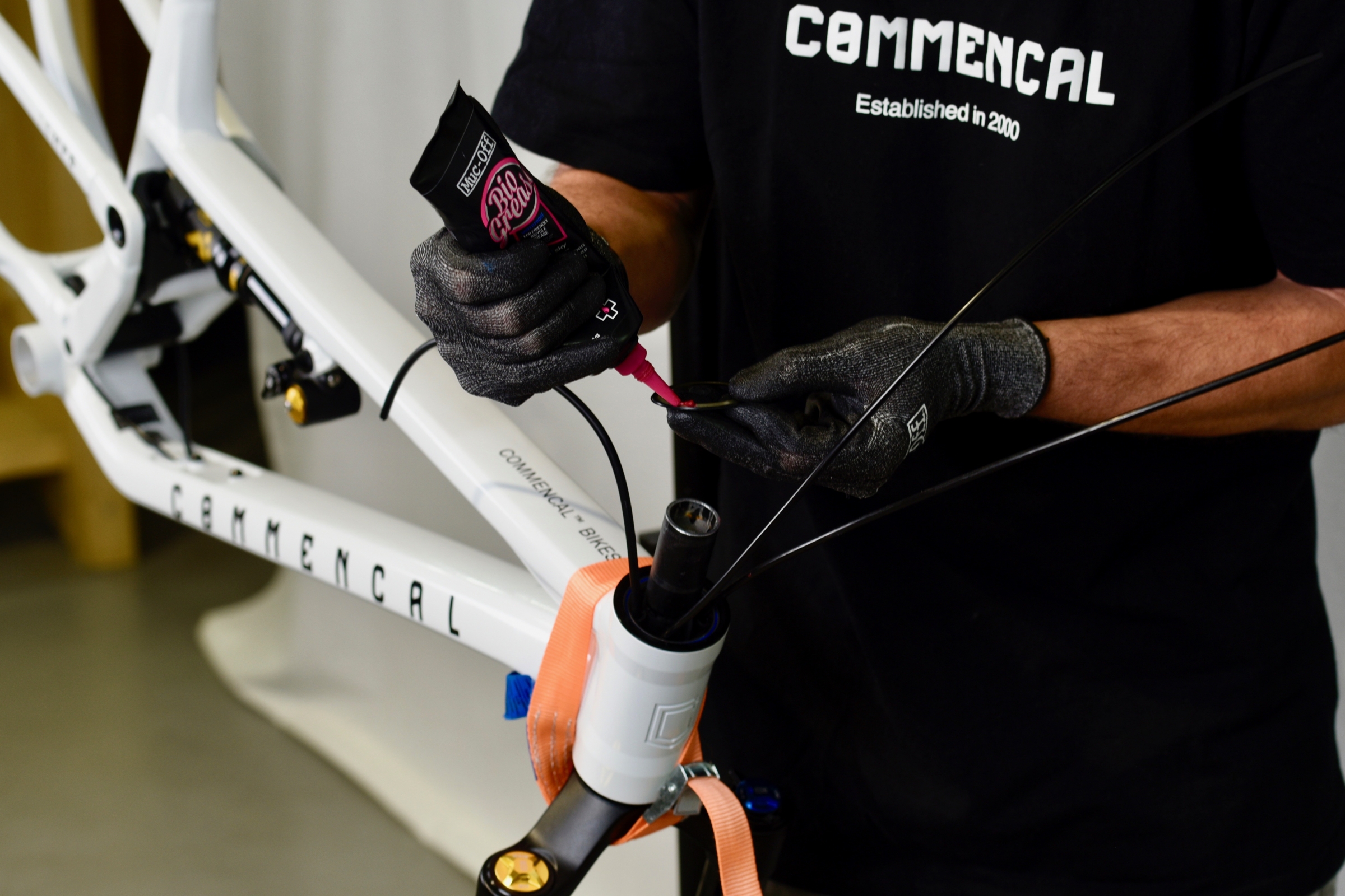
Grease smaller dust seal and install it on upper bearing.
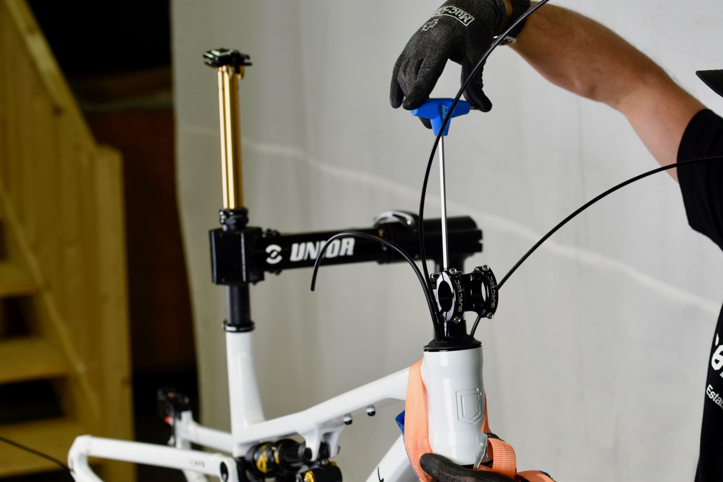
Tip: Use a strap to keep the fork in place while installing upper parts of the headset.
Clip on compression ring hook.
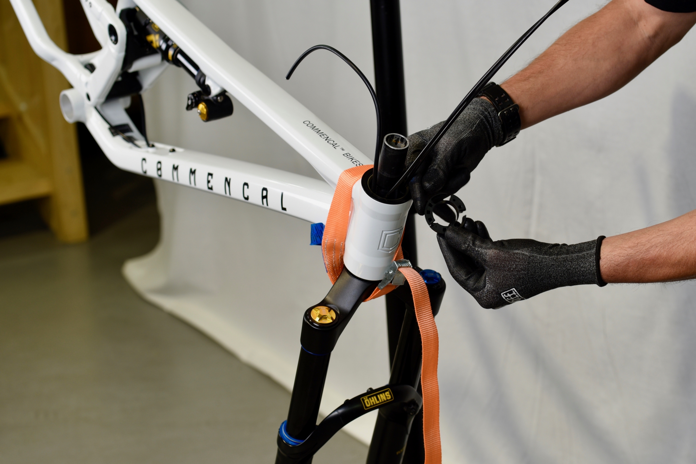
Install compression ring with housing placed in its channel.
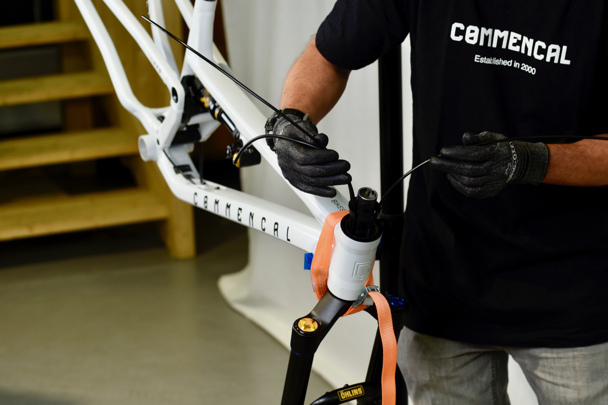
Now clip larger dust seal on the top cover.
Install top cover on the steerer with housing placed in its channel.
Make sure to align the plastic pins under the top cover, with corresponding holes on the compression ring.
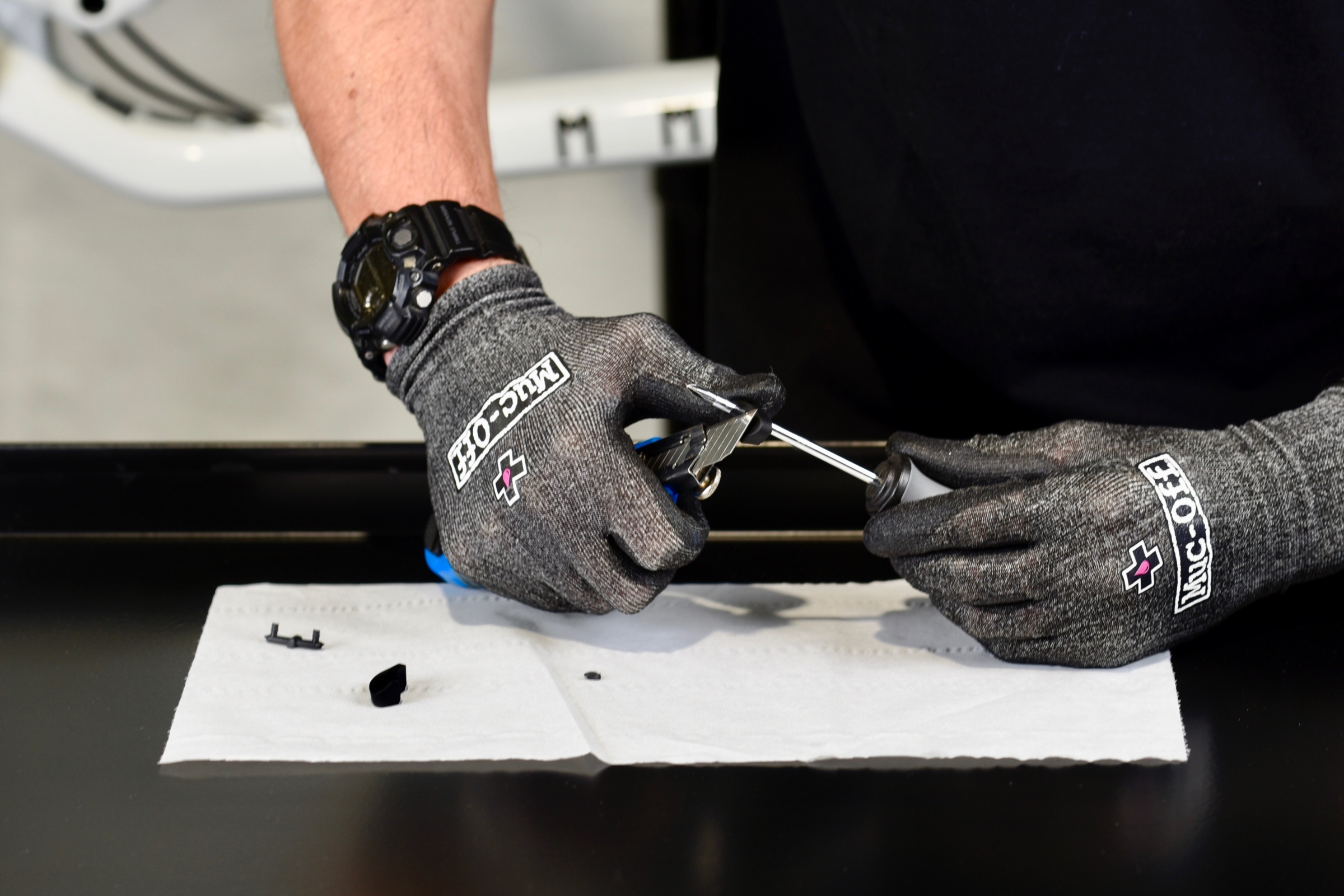
Use the Philips screwdriver to open rubber seals according to your setup.
Note: seals have a specific right and left side, make sure to identify them correctly.
Cut rubber excess using cutters.
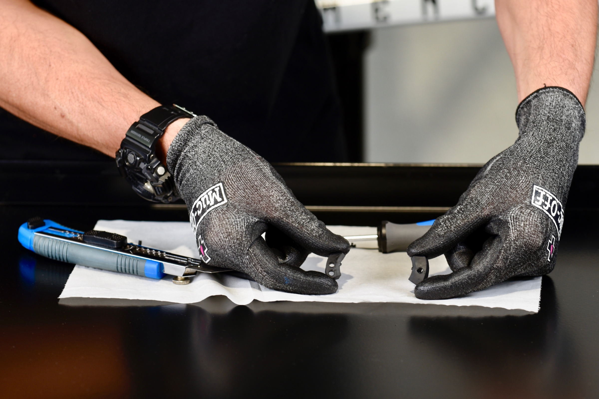
Your rubber seals are now ready to be installed.
Install rubber seals on housing.
Push rubber seals in the top cover.
Now install headset spacers, stem and top cap. Use a 5mm Allen key to screw top cap bolt.
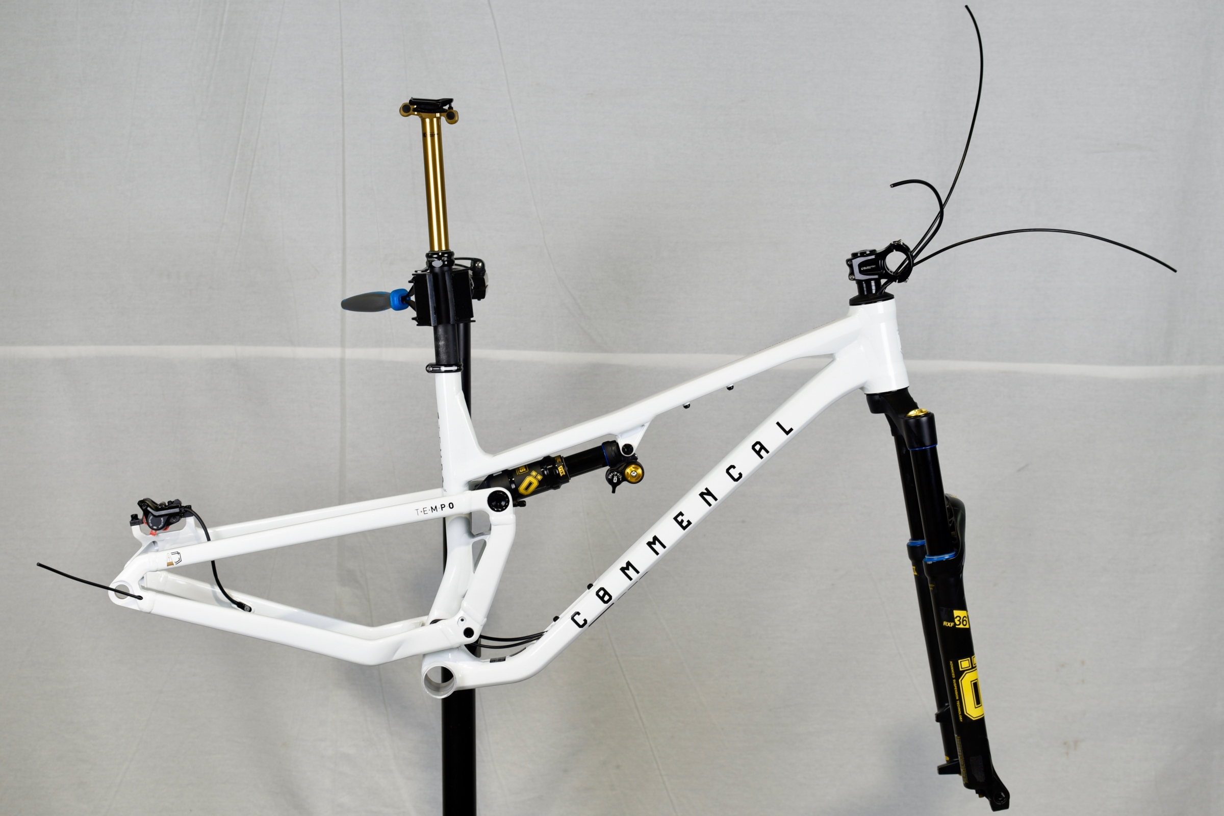
Your frame is now ready for the next step of the build with all housing routed in the frame and headset.
Fork and stem installed.
Make sure you follow the assembly and torque instructions specific to the different parts manufacturers.
Happy build!
And enjoy your Commencal T.E.M.P.O.


